- Document History
- Subscribe to RSS Feed
- Mark as New
- Mark as Read
- Bookmark
- Subscribe
- Printer Friendly Page
- Report to a Moderator
- Subscribe to RSS Feed
- Mark as New
- Mark as Read
- Bookmark
- Subscribe
- Printer Friendly Page
- Report to a Moderator
Overview
LabVIEW Communications System Design Suite provides a tool that helps users convert a floating point algorithm design to an equivalent fixed point algorithm design. Algorithms can be tested and optimized with floating point data. However, deploying them to an FPGA requires implementation with fixed point data. The use of fixed point data is more efficient in terms of FPGA resources and power consumption than floating point data. This example is an exercise that demonstrates the use of the fixed point conversion tool.
Description
This example will guide you through the design of a low-pass IIR filter that meets the following requirements:
- topology: elliptic
- order: 2
- sample frequency: 1 Hz
- cut-off frequency: 0.125 Hz
- passband ripple: 0.09 dB
The floating point design is provided and has already been tested and optimized to meet these requirements. You will use the conversion tool to produce a fixed point design that meets the same requirements.
The conversion tool makes initial suggestions for the fixed point data type configuration of each node on the block diagram. It makes this suggestion by ensuring that the signal-to-noise ratio (SNR) between the floating point representation of each node and its quantized fixed point representation stays above a user specified value in decibels (dB). When the suggested fixed point configuration is applied to each node, the resulting design may no longer meet the original requirements. The user can adjust the target SNR for all the nodes, or the fixed point configuration for a subset of nodes, iteratively until the fixed point design falls within the original requirements.
Figure 1 compares the frequency response of the floating point design (the red plot) with that of the fixed point design (the blue plot) after the initial suggestion is applied. The initial suggestions resulted in a design that does not meet requirements. Figure 2 shows the frequency response of the fixed point design after the user follows the in-exercise instructions to make iterative adjustments.
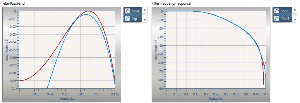
Figure 1: The "Filter frequency response" graph (right) shows the main lobe of the filter, which ends at 0.5 Hz, allowing sampling at 1 Hz. The "Filter Passband" graph (left) zooms into the passband to show the 0.125 Hz cut-off freqency and the 0.09 dB ripple.The fixed point design does not meet requirements
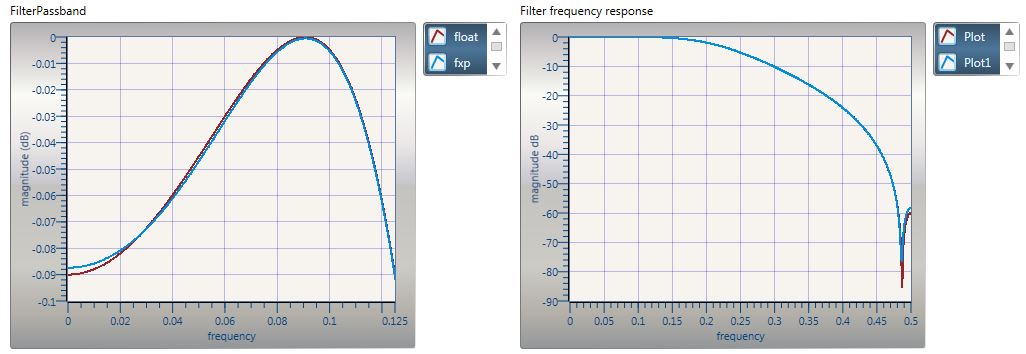
Figure 2: After iterative adjustments to the fixed point data type configuration of various nodes, the fixed point design finally falls within the requirements.
Steps to Implement or Execute Code:
1. Extract the contents of the file LP4.zip in the attachment.
2. Double click and open the file LP4.lvproject to open the LabVIEW Communications project for this exercise.
3. Follow the step-by-step instructions in the Guided Help window shown in Figure 3
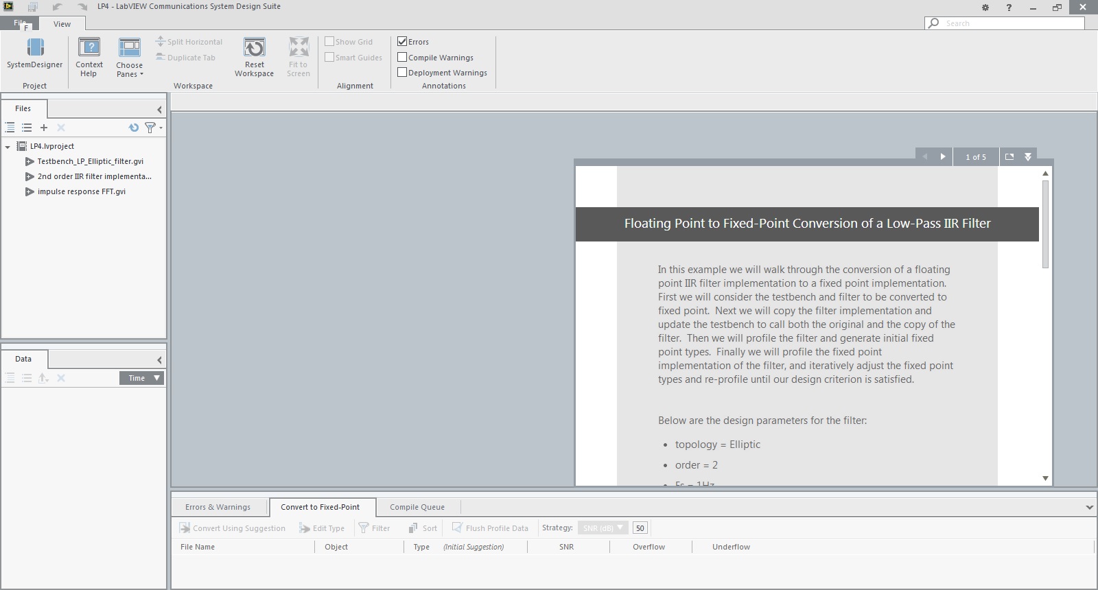
Figure 3: Follow the step-by-step instructions in the Guided Help window to complete the exercise.
Requirements
Software
- LabVIEW Communications System Design Suite 1.0
Hardware
- Not required
Click Here to discuss this and other examples on the LabVIEW Communications Discussion Forums.
Applications Engineer
National Instruments
http://www.ni.com/support
