- Subscribe to RSS Feed
- Mark Topic as New
- Mark Topic as Read
- Float this Topic for Current User
- Bookmark
- Subscribe
- Mute
- Printer Friendly Page
NI Power Electronics Control Design V Training Course
06-14-2014
05:42 PM
- last edited on
04-27-2025
12:03 PM
by
![]() Content Cleaner
Content Cleaner
- Mark as New
- Bookmark
- Subscribe
- Mute
- Subscribe to RSS Feed
- Permalink
- Report to a Moderator
Welcome to the NI Power Electronics Control Design V Training Course! The training material can be done in-person with physical hardware, or as self-paced software only exercises.
Learning Objectives
After completing the workshop material and related training courses, developers should be able to reliably design and deploy advanced power electronics control systems by following a standard, repeatable Design V Process. By completion, developers should be able to do the following:
- Use graphical programming techniques to design power electronics control systems for parallel execution in heterogeneous FPGA hardware.
- Perform time adaptive synchronized co-simulation (TASCS) to accurately simulate the dynamic interaction between FPGA control software and switched-mode power electronics circuitry.
- Utilize the NI General Purpose Inverter Controller (GPIC) reference design application template and a miniature-scale 3-phase back-to-back power converter for rapid control prototyping.
- Understand open source control algorithm IP cores for dead-time insertion, sine-triangle pulse width modulation, phase-lock-loop (PLL), AC induction motor V/f control, cascaded PID control, and more.
- Deploy FPGA-based control algorithms to high volume commercial deployment systems and compare simulated versus measured results.
- Simulate power electronics circuitry in real-time utilizing floating-point transfer function, state-space and automatic-conversion circuit solvers.
- Perform automated hardware-in-the-loop validation/verification and real-time testing of the embedded control system.
Compared to conventional development techniques, teams that have successfully mastered the LabVIEW RIO architecture reduce embedded control system development cost by at least 2-4 fold (over 114 person-month savings per design), focus a majority of their development time on high value tasks such as developing and validating proprietary IP, and outperform competitive products by utilizing the latest heterogeneous system on a chip (HSOC) technology for 40 to 74 fold higher performance per dollar compared to conventional monolithic DSPs and microprocessors.


Recommended Hardware
1. 784491-01 Development Kit which includes NI sbRIO-9607 Zynq-7020 GPIC (Thermal Kit, Power, Standoffs, Accessories, 90 Day Software)
2. GPIC Power Converter Control Development System (Mini-Scale SKiiP3 Replica Back-to-Back Converter)
Note: All of the co-simulation examples in the training course can be completed without having physical hardware. Waveforms captured using the inverter control development boards are saved and can be played back to compare simulated versus physical results.
What to Install
The recommended development software for power electronics control is the NI Software Platform Bundle which is orderable using part number 784333-35. This includes the complete NI design V toolchain for power electronics control development, co-simulation, testing and deployment.
The NI development tools can be downloaded for fully functional 30-45 day evaluation using these links: LabVIEW 2015 HIL & Real-Time Test Suite + NI CompactRIO 15.0 Device Drivers + NI Circuit Design Suite 14.0 Full or Pro (Multisim/Ultiboard) + LabVIEW Electrical Power Suite 2015
What to install (recommended minimum set):
- LabVIEW Full or Professional. Notes: Install the 32-bit version of LabVIEW. Use Windows 7 OS. IP Builder, Xilinx Coregen and Xilinx Compile Tools for LabVIEW FPGA are not supported with Windows 8 nor Windows 8.1 (more info).
- LabVIEW Real-Time Module
- LabVIEW FPGA Module
- LabVIEW Control Design and Simulation Module
- NI RIO>NI CompactRIO 15.0 (Driver Support>Reconfigurable I/O)
- NI Multisim + Ultiboard Circuit Design Suite. IMPORTANT: When installing Multisim, select the option to install the co-simulation plug-in for LabVIEW 2014. You do not need to have LabVIEW 2014 installed. Then follow the instructions below to move the plug-ins to LabVIEW 2015 directories.
- LabVIEW Electrical Power Suite
- Xilinx Compilation Tools for Vivado 2014.4* Note: Needed if you are using sbRIO-9607 Zynq-7020 controller for GPIC and using IP Builder, modifying Xilinx Coregen blocks, or performing local compiles. Requires Windows 7 OS. Note that new open source IP cores from NI Systems Engineering are based on IP Builder.
- Xilinx Compilation Tools for ISE 14.7* Note: Needed if you are using sbRIO-9606 Spartan-6 controller for GPIC and using IP Builder, modifying Xilinx Coregen blocks, or performing local compiles. Requires Windows 7 OS. Note that new open source IP cores from NI Systems Engineering are based on IP Builder.
- Sign up for NI Cloud Compile Service: Note: This is included with NI Software Subscription Package (SSP) and a free 90 day trial is available. NI Cloud Compile Service is now included with SSP.
- Explore online training resources. Note: Online training is now included with NI Standard Service Program (SSP). Online training is now included with SSP.
IMPORTANT: Co-simulation is available and supported for LabVIEW 2015 and Multisim 14 but requires some special steps to enable it. Be sure to install the LabVIEW Control Design and Simulation Module 2015 for LabVIEW 2015. When you install Multisim 14, be sure to install the co-simulation plug-in for LabVIEW 2014. You do not need to have LabVIEW 2014 installed. Then copy the folders and files to the equivalent LabVIEW 2015 directory locations as explained below.
The trick is that, after installing the co-simulation plug in, you need to copy the folders and files below from the LabVIEW 2014 directory to the equivalent LabVIEW 2015 directory:
C:\Program Files\National Instruments\LabVIEW 2014\vi.lib\Simulation\EMI\Plugins\Multisim Design
C:\Program Files\National Instruments\LabVIEW 2014\help\msmcosim.chm
C:\Program Files\National Instruments\LabVIEW 2014\help\msmcosim.txt
IMPORTANT NOTE:
- You must keep your Multisim files and LabVIEW co-simulation VI files in the same directory path. For co-simulation with Multisim 14, the Multisim circuit design files must be located in the same directory path as the LabVIEW co-simulation VI. Otherwise a crash will occur if the Multisim file path is changed. This is a known issue that will be fixed in the future. In the mean time, the workaround is straightforward: You must keep your Multisim files and LabVIEW co-simulation VI files in the same directory path.
Getting Started Instructions
1. The minimum set of development tools to download and install is: LabVIEW Full or Pro, LabVIEW Real-Time, LabVIEW FPGA, NI Control Design and Simulation Module, NI Multisim, Compilation Tools for Vivado 2013.4 (sbRIO-9607 GPIC), Compilation Tools for ISE 14.7 (sbRIO-9606 GPIC), NI CompactRIO 15.0, LabVIEW Electrical Power Suite
2. Download and install the training software for LabVIEW 2015 or LabVIEW 2014 (NI GPIC Reference Design Project). You must unzip to a short directory path such as C:\LabVIEW 2015 (not desktop) using 7-Zip or WinZip (not the default Windows Zip archive utility.)
If you unzip using the recommended directory location, the LabVIEW Project file to use with this training course will be located here:
C:\LabVIEW 2015\GPIC\GPIC Reference Design\GPIC Reference Design LabVIEW 2015.lvproj
3. Download the instruction manual.
4. Download the instructor slides (optional).
6. View the online training videos (below). Reply to this discussion thread with technical questions, or contact your local NI office with sales questions.
Pre-Requisites
1. Use the NI web downloaders to install the latest version of the NI development tools and GPIC Reference Design training software on your computer (see the Instructions and Resources section above).
2. Review the introduction to LabVIEW tutorials:
3. Complete the introduction to Multisim exercise:
Introduction to Multisim: Learn to Capture and Simulate in Less Than 30 Minutes
4. Complete the introduction to FPGA co-simulation exercise, beginning with part 3.
If you hit a snag or have questions, make a note of it and move on to the next exercise. Post your questions to this discussion thread when finished.
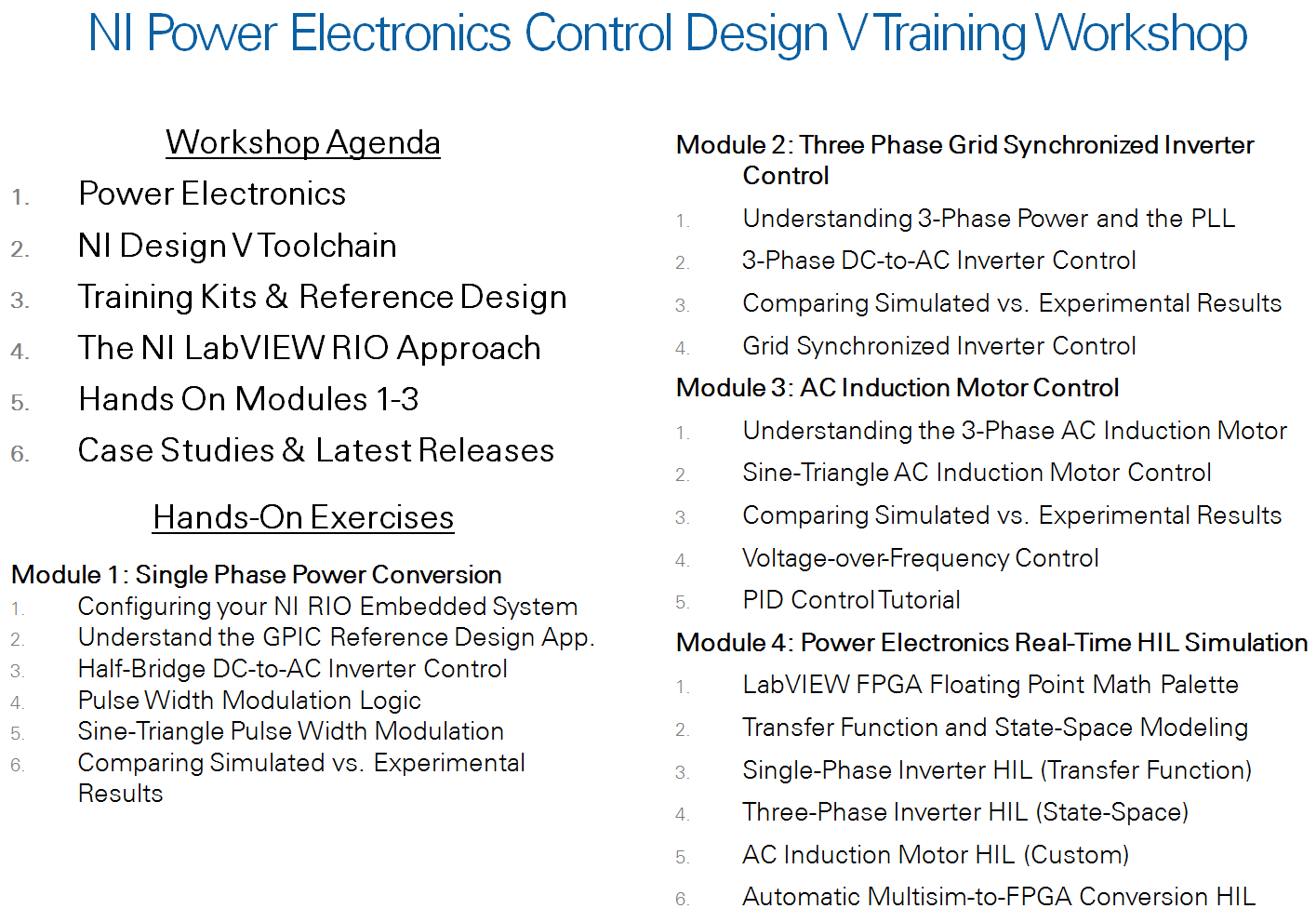
Hands-On Exercises
Module 1: Single Phase Power Conversion
- Configuring your NI RIO Embedded System (requires hardware)
STEPS:
1. Disable WiFi
2. Launch NI MAX
3. Refresh Remote Systems
4. Format Disk
5. Install Firmware - see list of items below depending on whether you are using the sbRIO-9607 or sbRIO-9606 controller for the GPIC:
sbRIO-9607 Controller
LabVIEW RT Add-Ons
• NI System Configuration
• System State Publisher
Network I/O
• Network Streams
Protocols and Buses
• NI-Watchdog
• Legacy FTP Server (deprecated)
sbRIO-9606 Controller
LabVIEW RT Add-Ons
• NI System Configuration
• System State Publisher
Network I/O
• Network Streams
Protocols and Buses
• NI-Watchdog
5. Set LV Project IP address
6. Connect and Deploy the Control Application
2. Understand the GPIC Reference Design Application
3. Half-Bridge DC-to-AC Inverter Control
4. Pulse Width Modulation Logic
5. Sine-Triangle Pulse Width Modulation
6. Comparing Simulated vs. Experimental Results
Module 2: Three Phase Grid Synchronized Inverter Control
- Understanding 3-Phase Power and the Phase Lock Loop
- 3-Phase DC-to-AC Inverter Control
- Comparing Simulated vs. Experimental Results
- Grid Synchronized Inverter Control
Module 3: AC Induction Motor Control
- Understanding the 3-Phase AC Induction Motor
- Sine-Triangle AC Induction Motor Control
- Comparing Simulated vs. Experimental Results
- Voltage-over-Frequency Control
- PID Control Tutorial
Module 4: Power Electronics Real-Time HIL Simulation
- LabVIEW FPGA Floating Point Math Palette
- Transfer Function and State-Space Modeling
- Single-Phase Inverter HIL (Transfer Function)
- Three-Phase Inverter HIL (State-Space)
- AC Induction Motor HIL (Custom)
- Automatic Multisim-to-FPGA Conversion HIL
Questions or comments? Reply to this discussion thread.
07-21-2014 01:04 PM
- Mark as New
- Bookmark
- Subscribe
- Mute
- Subscribe to RSS Feed
- Permalink
- Report to a Moderator
How often will the video tutorials be uploaded? Its been quite sometime since the last upload.
07-21-2014 06:56 PM
- Mark as New
- Bookmark
- Subscribe
- Mute
- Subscribe to RSS Feed
- Permalink
- Report to a Moderator
Your post is good motivation. Thanks for your interest. Module 1, Exercise 2 (Exploring the GPIC Reference Design Application) has been added to the instruction manual and a tutorial video is posted above. The GPIC reference design code is meant to be a simplified skeleton application to use as a starting point for development-- remove the pieces you don't need and add your own proprietary IP algorithms.
BTW, let me know if there are other topics or modules that you'd like to see sooner rather than later - they don't have to be posted in the default order.
09-03-2014 08:54 PM
- Mark as New
- Bookmark
- Subscribe
- Mute
- Subscribe to RSS Feed
- Permalink
- Report to a Moderator
Thank you Brian, I will try it out.
09-09-2014 09:59 AM
- Mark as New
- Bookmark
- Subscribe
- Mute
- Subscribe to RSS Feed
- Permalink
- Report to a Moderator
Brian,
Great video, learning good stuff from these reference designs.
I think tutorials on Module 4 listed above, or any other references and tutorials towards creating more custom power circuits and systems in MultiSim and associated VIs, and then running inverter control via the sbRIO FPGA for HIL testing and prototyping would be of great help to get more complex inverter system development jump started.
Thanks!
10-06-2014 09:37 AM
- Mark as New
- Bookmark
- Subscribe
- Mute
- Subscribe to RSS Feed
- Permalink
- Report to a Moderator
Will do. In the mean time, I want to let you know that an updated version of the Heterogeneous FPGA Graphical Floating Point Toolkit is available. There is a white paper explaining how to use it, including the real-time HIL simulation examples for power electronics circuits using transfer function and state-space model solvers. With the availability of these new tools, you can turn pretty much any NI LabVIEW RIO target into a real-time HIL simulator to facilitate development-- an alternative to spending hundreds of thousands of dollars on a specialized real-time HIL system.
Also note that the GPIC back-to-back converter research board is designed to easily support HIL signals replacing physical sensor feedback. By removing all of the analog input jumpers under the board, you can disconnect the physical sensors and wire in HIL simulated sensor feedback to connector U24. On the other hand, if the jumpers are installed then all of the conditioned sensor signals (scaled down) are available for monitoring by connecting a scope to U24 terminals. For HIL access to the digital gate command signals, they are buffered out on the LVTTL lines of the by default in the GPIC Reference Design example code.
11-19-2014 08:01 AM
- Mark as New
- Bookmark
- Subscribe
- Mute
- Subscribe to RSS Feed
- Permalink
- Report to a Moderator
This course is very helpful and the Research Board is a great tool!
I have a question regarding the output filter and load. The neutral point of both the capacitors and the resistances is connected to PGND. Wont that create homopolar current circulation unless the 3-phase system is totally balanced? I guess it's either this or having a wobbly voltage neutral point (with respect to ground), right?
What are the proposed filter values? I've seen 100uF for capacitors on schematics, but the capacitors that seem to be shipped are 47uF. Also just learnt that you could have bi-polar electrolytic capacitors.
Additionally, is it possible to have the GPIC Reference Design code available for 2013? Not a requirement, but could be handy.
Thanks!
12-05-2014 03:49 PM
- Mark as New
- Bookmark
- Subscribe
- Mute
- Subscribe to RSS Feed
- Permalink
- Report to a Moderator
I currently have the LabVIEW 2013 sp1 and all other required tools installed. Then I downloaded the GPIC reference design project only to find out it is created by LabVIEW 2014 and I can't open it. Is there a link so I can download a previous version of the project? Thank you!
12-05-2014 05:11 PM
- Mark as New
- Bookmark
- Subscribe
- Mute
- Subscribe to RSS Feed
- Permalink
- Report to a Moderator
You bet. The LabVIEW 2013 archive version is linked below. To extract, you must use 7-Zip or Winzip (not Windows built in ZIP archive utility) and you must unzip to a very short path such as "C:\PowerDev\" (not to your desktop):
ftp://ftp.ni.com/evaluation/powerdev/training/GPICReferenceDesign2013.zip
12-08-2014 03:38 PM
- Mark as New
- Bookmark
- Subscribe
- Mute
- Subscribe to RSS Feed
- Permalink
- Report to a Moderator
Thank you for your reply!
I followed the link and got the zip file named ‘GPICReferenceDesign2013.zip’. However, after I unzip it, the project was still created by 2014.
