- Document History
- Subscribe to RSS Feed
- Mark as New
- Mark as Read
- Bookmark
- Subscribe
- Printer Friendly Page
- Report to a Moderator
- Subscribe to RSS Feed
- Mark as New
- Mark as Read
- Bookmark
- Subscribe
- Printer Friendly Page
- Report to a Moderator
Overview
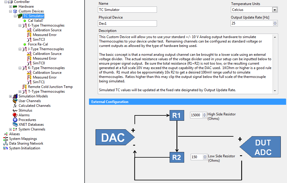
This custom device allows the user to configure any standard +/-10V analog outputs to behave as a simulated Thermocouple. This is done by inserting a 2 resistor voltage divider on the output of each channel. Sources of error are calibrated out through the use of a separate temperature measuring device that acts as feedback to the custom device. Any combination of J, K ,T, E , N , B, R and S type thermocouples are supported, and unused channels may be configured for voltage (or current) output as required.
Requirements
Hardware:
Any +/-10V Analog Output channel that uses the NI DAQmx Driver can be used with this custom device. This includes M and X series Multifunction DAQ devices provided that have Analog Outputs, provided the Ananlog Outputs are not also configured as DAQ channels in the DAQ section of the System Explorer. The ideal device for higher channel counts is a dedicated Analog Output board in the 67xx family. The PCI/PXI-6704 is the only board that supports current outputs.
Software:
NI Veristand 2011 (Source code can be compiled for previous versions)
Instructions for Use
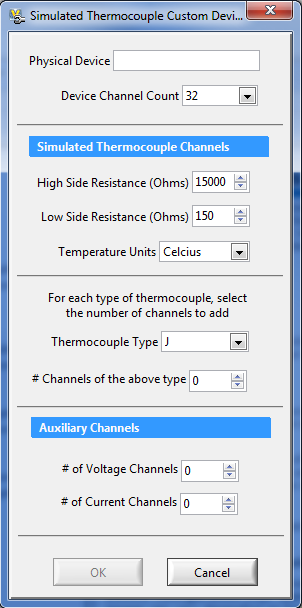
When initializing a new custom device, you will be prompted to enter the physical device ID, general settings, and the number of channels to create. After pressing OK, the channels will be initialized. You can add additional channels later by right clicking the custom device and selecting Add Channels or by pressing the Add Channels button on the task bar. Individual channels and sections can be configured as required via their corresponding pages. The value applied to each thermocouple channel is the temperature that you would like the Device under Test to see, were a real thermocouple attached.
Calibration Explained
Each TC type has its own calibration. The device will output a linear sweep of voltages (on one channel) corresonding to the range of temperatures for that TC type. This TC channel must be externally connected to a Thermocouple measurement device such as a PXIe-4353, as well as the Device Under Test. Within the system explorer the measured temperature on that channel must be mapped to the corresponding Calibration Channel for that TC type. This froms a closed feedback loop on which to calibrate. (connecting a TC to multiple measurement devices does not affect the measured temperature on either device)
After some settling time, the value on the corresponding Calibration Channel is read to produce an error for that temperature output value. The settling time, as well as the number of points within the temperature sweep can be configured on each sections Calibration channel page. (For multiple TC types - the largest number of points and settling time is chosen for all channels) The resulting aggregate of errors produces a lookup table that is used to interpolate the correct voltage output for any desired temperature.
The device will automatically calibrate upon deployment. When the calibration is complete, the Cal Valid channel will be set to 1. The user can set Force Re-cal to 1 at any time to reperform the Calibration cycle on all channels. The Remote CJC Temperature channel can be used if you suspect that the local measured CJC temperature differs greatly from the Device Under Test, or if you expect it to vary significantly over the course of a test. If no value is applied, the the local CJC temperature at the time of calibration is seen simply as an offset and calibrated out.
Accuracy
The accuracy is largely dependent on the number of calibration points obtained. This is particularly true at the upper and lower end of the Thermocuoples range. The default number of points is 25, or 40 degree increments over a range of 1000 degrees. Typically, in the middle 80% of the range one could expect the outputted temperature to be off by no more than a few tenths of a degree - which is better than most real thermocouples. More points can always be calibrated for better and more consistent accuracy over the entire range of the TC.

This add-on is provided as open-source software. If it does not meet your exact specification, you are encouraged to modify the source code to meet your needs. It is not officially supported by National Instruments.
If you encounter a problem with this add-on, or if you have suggestions for a future revision, please post to the forum for this add-on Simulated Thermocouple Custom Device Feedback. You must use this feedback forum for support. Do not call National Instruments for support for this add-on.
National Instruments does not support this code or guarantee its quality in any way. THIS EXAMPLE PROGRAM IS PROVIDED "AS IS" WITHOUT WARRANTY OF ANY KIND AND SUBJECT TO CERTAIN RESTRICTIONS AS MORE SPECIFICALLY SET FORTH IN NI.COM'S TERMS OF USE (http://ni.com/legal/termsofuse/unitedstates/us/).
Product Manager - NI VeriStand and Model Interface Toolkit
National Instruments
- Mark as Read
- Mark as New
- Bookmark
- Permalink
- Report to a Moderator
Hi,
I dont know if you could help me with my questions.
My customer wants to simulate TC to test his setup (ofen) after a couple of weeks.
We suggested to use a SMU, but this meight be to expensive for the customer.
Currently we used a cdaq approach but I have doubt that we can use a standard analog output module with a range of +-10VDC in order to simulate a Thermocouple.
Could your approch also be used in LV with cDAQ?
And what is the expected accurary?
Thanks
bernhard
- Mark as Read
- Mark as New
- Bookmark
- Permalink
- Report to a Moderator
Rossi,
I will post a response on the Feedback Forum for the Simulated Thermocouple Custom Device
Andrew
