- Subscribe to RSS Feed
- Mark Topic as New
- Mark Topic as Read
- Float this Topic for Current User
- Bookmark
- Subscribe
- Mute
- Printer Friendly Page
Zero crossing detector simulation
10-02-2012 07:27 AM
- Mark as New
- Bookmark
- Subscribe
- Mute
- Subscribe to RSS Feed
- Permalink
- Report to a Moderator
hello every one,
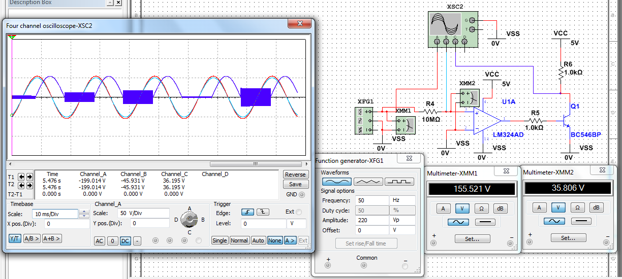
I'm trying to simulate a zero-crossing detector circuit on Multisim but it gives me a strange results !
I attached both the circuit and the result.
can anyone help me with that ?
Thanks,
Ahmed Elsayed
10-02-2012 09:15 AM
- Mark as New
- Bookmark
- Subscribe
- Mute
- Subscribe to RSS Feed
- Permalink
- Report to a Moderator
hello Ahmed Elsayed,
I think the input voltage of the OP may not exceed approx. 30 V. The amplitude of the sine input seemes to be more than 200 V.
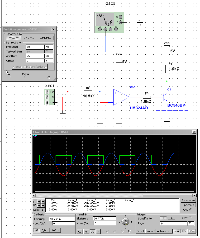
With less or equal 25 V it will function very well.
I hope this helps.......

10-03-2012 06:44 AM
- Mark as New
- Bookmark
- Subscribe
- Mute
- Subscribe to RSS Feed
- Permalink
- Report to a Moderator
Hello Ienny
Thanks for replying, i do like you did in your attached image but it still give me strange results.
i beleive it's an error in the ciruit altough it is a simple one -comparator in any test book- and it is not a multisim bug !
here is the second exp. results.

Thanks for help.
10-04-2012 03:39 AM
- Mark as New
- Bookmark
- Subscribe
- Mute
- Subscribe to RSS Feed
- Permalink
- Report to a Moderator
Hello Ahmed,
I think your input voltage is still to high. I cannot reproduce your results.
Which model are you using for the LM324AD? There are six different models available in the main database.
I used the default model Motorola/LM224_6.
The model LM324_2 has no limitations with respect to the supply voltage of the OpAmp.
Hope this helps....
lenny
10-04-2012 05:19 AM
- Mark as New
- Bookmark
- Subscribe
- Mute
- Subscribe to RSS Feed
- Permalink
- Report to a Moderator
Hello Ienny,
thanks for trying to help. 'm using the same model you use (Motorola/LM224_6) !
if you could attach your multisim file, i may figure it out.
10-09-2012 05:52 AM
- Mark as New
- Bookmark
- Subscribe
- Mute
- Subscribe to RSS Feed
- Permalink
- Report to a Moderator
Hello Ahmed,
Itried to answer to your e-mail and to attache the multisim file but i got an error from the NI server.
I don't know how to attache the file to my response at the discussion forum. There are only image or video files allowed.
Perhaps you can send me a private message with your email address and I will send you the multisim file immediatly.
03-21-2013 12:52 AM
- Mark as New
- Bookmark
- Subscribe
- Mute
- Subscribe to RSS Feed
- Permalink
- Report to a Moderator
Hi, what chip will you use if we have input frequency about 20Mhz of above zero crossing detector circuit? I have this challenging this moment. Anyone know this please help. Thanks
