- Subscribe to RSS Feed
- Mark Topic as New
- Mark Topic as Read
- Float this Topic for Current User
- Bookmark
- Subscribe
- Mute
- Printer Friendly Page
How to connect a quadrature encoder to PCI-6221 DAQ (37 pin)
10-29-2007 07:48 PM
- Mark as New
- Bookmark
- Subscribe
- Mute
- Subscribe to RSS Feed
- Permalink
- Report to a Moderator
10-30-2007 07:11 AM
- Mark as New
- Bookmark
- Subscribe
- Mute
- Subscribe to RSS Feed
- Permalink
- Report to a Moderator
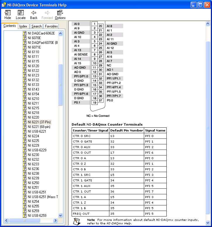
You can see the wire diagrams on the product manual of the card : for example, for the counter0 :
pin +A on the pfi0 (pin 13 of the card)
pin +B on the pfi2 (pin 33 of the card)
pin +Z on the pfi1 (pin 32 of the card)
I don't know the link with matlab, but it's very easy to use a quad encoder with labview.
Regards
10-30-2007 07:13 AM
- Mark as New
- Bookmark
- Subscribe
- Mute
- Subscribe to RSS Feed
- Permalink
- Report to a Moderator
10-30-2007 09:51 AM
- Mark as New
- Bookmark
- Subscribe
- Mute
- Subscribe to RSS Feed
- Permalink
- Report to a Moderator
11-01-2007 04:52 AM - edited 11-01-2007 04:52 AM
- Mark as New
- Bookmark
- Subscribe
- Mute
- Subscribe to RSS Feed
- Permalink
- Report to a Moderator
If you are using the 6221 (37 pin) I do not see A-, B- and Z- in the pin out. The 6221 pin-out shows that A (pin 13) is the counter source. This is the what you connect the signal you are attempting to count. Z (pin 32) is the counter gate. When the gate signal is high, the signal connected to the source will be counted. B (pin 33) is the Aux line. This line determines whether the counter increments or decrements. See the chapter 7 of User manual for this device to further understand what type of counter operations are possible.
I hope this helps.
Message Edited by Ima U on 11-01-2007 04:54 AM
Ima
Applications Engineer
National Instruments
LabVIEW Introduction Course - Six Hours
Getting Started with NI-DAQmx
11-01-2007 09:14 AM
- Mark as New
- Bookmark
- Subscribe
- Mute
- Subscribe to RSS Feed
- Permalink
- Report to a Moderator
Just adding a small correction: for the specific case of encoder position measurement, the Z signal connected to the counter gate doesn't work as described by Ima in the last post. The Z signal of a rotating encoder will be a single narrow pulse that repeats at the same shaft angle each revolution. The counter task may be programmed to force the angle measurement to reset to 0 on each of these pulses -- some apps prefer a relative angle rather than tracking continuous rotation.
So, in encoder position measurement, the A and B signal transitions determine whether the count increments or decrements. The Z pulse may be ignored or it may be used to cause the count to reset to 0. (Technically, you could reset to some other value if desired, but this is less common.)
-Kevin P.
