- Subscribe to RSS Feed
- Mark Topic as New
- Mark Topic as Read
- Float this Topic for Current User
- Bookmark
- Subscribe
- Mute
- Printer Friendly Page
Best settings for low noise using a 5922 Scope
05-25-2007 08:19 AM
- Mark as New
- Bookmark
- Subscribe
- Mute
- Subscribe to RSS Feed
- Permalink
- Report to a Moderator
05-29-2007 06:07 PM
- Mark as New
- Bookmark
- Subscribe
- Mute
- Subscribe to RSS Feed
- Permalink
- Report to a Moderator
Specifications mention that you should be getting around 3.4 uV RMS. Is the value you present the peak or the average?
I am assuming your antenna is 50 Ohms, make sure you select that on the card. For the sample rate, I see you need 150 kHz as the high end, if you want the best accuracy, use the full 24 bits (keep the sampling rate below 500 k). Finally, make sure you have the anti alias filter set as specifications (0.4 x Sampling Rate).
Finally, if you have Spectral Measurements Toolkit, there are many examples to get lots of spectral information and measurements about the input signal.
Hope this helps,
RF SW Engineering R&D
National Instruments
05-30-2007 12:49 PM
- Mark as New
- Bookmark
- Subscribe
- Mute
- Subscribe to RSS Feed
- Permalink
- Report to a Moderator
Thanks. I have the input filtering to -1. I guess this means no filtering. Is the antialliasing filter always on? so I manually (through a code constant) set this to 0.43x DAQ rate? I started from an example which had this set to -1. I am sampling at 500KHz since this is in the requirement docs. The 0.0001 is peak values and the antennea is 50Ohms. will the change in filtering value fix this?
Paul
05-31-2007 05:11 PM - edited 05-31-2007 05:11 PM
- Mark as New
- Bookmark
- Subscribe
- Mute
- Subscribe to RSS Feed
- Permalink
- Report to a Moderator
I think this number (100 uV) is the peak time domain signal correct? If you connect your device to a 50 Ohm terminator, you should get what specifications are saying. Since you are looking at a time domain data, you will see the DC + AC. Only DC is 100 uV + some % (link for details).
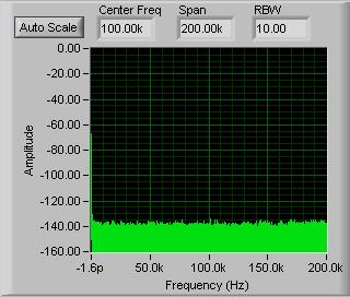
This means that the value you are seeing is normal. Now, the value of 3.4 uV is first AC and second for 50kS/s. Take a look at the spectrum when connected to a 50 Terminator
What is exactly what you are trying to accomplish that this "noise" is important?
Message Edited by Yardov on 05-31-2007 05:12 PM
RF SW Engineering R&D
National Instruments
06-01-2007 07:10 AM
- Mark as New
- Bookmark
- Subscribe
- Mute
- Subscribe to RSS Feed
- Permalink
- Report to a Moderator
Thanks I will play with it when I get to the client site again. I will make sure the filtering is on and retest the unit I will also try using a 50Ohm termination.
Paul
