ni.com is currently undergoing scheduled maintenance.
Some services may be unavailable at this time. Please contact us for help or try again later.
- Subscribe to RSS Feed
- Mark Topic as New
- Mark Topic as Read
- Float this Topic for Current User
- Bookmark
- Subscribe
- Mute
- Printer Friendly Page
Question about the data acquisition.
Solved!02-05-2022 10:03 AM
- Mark as New
- Bookmark
- Subscribe
- Mute
- Subscribe to RSS Feed
- Permalink
- Report to a Moderator
Hello,


Solved! Go to Solution.
02-05-2022 02:56 PM
- Mark as New
- Bookmark
- Subscribe
- Mute
- Subscribe to RSS Feed
- Permalink
- Report to a Moderator
1. You should be using a DMA FIFO to pass your data from the FPGA to the host. Otherwise, you are just getting the values when the host just happens to decide to look at the variable. This is your main timing issue.
2. Excel is limited in how many lines it can show. If you want to see more from a TDMS file, then you will want to look at either DIAdem from NI or Scout from Signal.X.
I would have to do some major digging to figure out how to really interface with your FlexRIO. Not an architecture I would recommend for a newbie.
There are only two ways to tell somebody thanks: Kudos and Marked Solutions
Unofficial Forum Rules and Guidelines
"Not that we are sufficient in ourselves to claim anything as coming from us, but our sufficiency is from God" - 2 Corinthians 3:5
02-05-2022 05:29 PM
- Mark as New
- Bookmark
- Subscribe
- Mute
- Subscribe to RSS Feed
- Permalink
- Report to a Moderator
Open, run, and review all of the examples listed here: https://zone.ni.com/reference/en-XX/help/372614J-01/friotransamr/5781_transceiver_clipref/
Certified LabVIEW Architect, Certified Professional Instructor
ALE Consultants
Introduction to LabVIEW FPGA for RF, Radar, and Electronic Warfare Applications
02-07-2022 02:23 PM
- Mark as New
- Bookmark
- Subscribe
- Mute
- Subscribe to RSS Feed
- Permalink
- Report to a Moderator
Hello,
Here are some thoughts and suggestions on your issue:
- The 100MHz clock is the sample clock for the ADCs in the adapter module. The I/O is being measured at that speed, and then the FPGA passes the data to a DMA FIFO to stream it to RAM on the computer.
- If you don’t read it out of memory fast enough, the buffer will fill up, and samples will start being over written.
- The 40MHz is the main rate that the LabVIEW FPGA block diagram is compiled at, but, certain sections of code can run faster than that, using the Single-Cycle Timed Loop structure. (The 40MHz clock is in the FPGA hardware, not the computer)
- My guess is that you aren’t reading out of the DMA channel on the Host side (Windows PC) fast enough. One way around that is to add another loop, just to read data from the DMA channel, and then pass the data to a separate loop to do any math or visualization.
- It's important to note that you mentioned DMA channels in your post, but the screenshot shows a Read/Write node. That's likely causing the noise and lost samples in your signal.
- You can have parallel loops and use FIFOs/Queues in Windows to pass data between your acquisition loop, your loop for processing and visualizing data, and writing data to disk.
- You could add timers and shift registers to the parallel loops, to benchmark loop speeds, and track down the functions that are taking the longest to execute.
- You can also allocate more memory and read a larger number of samples at a time, to read in larger blocks and reduce bottlenecks.
Regards,
Vineet
02-11-2022 03:49 PM
- Mark as New
- Bookmark
- Subscribe
- Mute
- Subscribe to RSS Feed
- Permalink
- Report to a Moderator
Hello crossrulz,
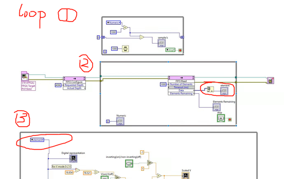
Thanks for your suggestion! I have tried to use the DMA FIFO to pass the data, and my new block diagram is shown below. The size of the FPGA DMA FIFO is 1024 and in the host end I set the FIFO depth as 4096 and want to read 1000 data at a time.
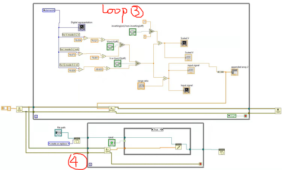
What I want to do is like what Vineet said below, to put the DMA channel in a single loop, the math calculation in another loop, and pass the data to the TDMS file in a third loop. However, as the data output from the DMA channel is in the form of 1D array and it seems like I can not directly use the array to do the mathematical calculation in loop 3, I want to extract the elements in the array to do the math calculation and present them on the waveform. I use the 'index array' function, but I think it may only give me the first element of the array, right? But if it is not feasible, what should I do, or which function should I use without changing the function in loop 3?
Another problem I met is the loop and sampling time. I use the loop one to measure the sampling time by measuring the number of iterations of loop 2 per second, multiplied by 1000 (as I set the number of element as 1000 in the DMA channel). What I get is about 400k to 500k samples/s if I do not write data to the TDMS file in loop 4. If I enable the boolean button and write data to the TDMS file, the sampling rate increases to 1M Sample/s. Why is there such a difference?
When I observe the TDMS file, I found the speed is much slower than the sampling rate I measured. For example, I run the program and write to the TDMS file for 10 seconds, I only get less than 1000000 data, which means the data speed into the file is less than 100 K/s and it is much slower than the sampling rate. Is there anything that I did wrong in my program?
02-14-2022 04:43 AM
- Mark as New
- Bookmark
- Subscribe
- Mute
- Subscribe to RSS Feed
- Permalink
- Report to a Moderator
And this is my VIs if necessary.
02-14-2022 10:57 AM
- Mark as New
- Bookmark
- Subscribe
- Mute
- Subscribe to RSS Feed
- Permalink
- Report to a Moderator
Hello,
I think you're getting closer, but here are a few things to watch out for:
- You're correct that using Index Array is only providing 1 element at a time. Try putting the full 1000 element 1D array into a Queue, to pass it to your second loop, instead of using a single local variable.
- You can monitor elements remaining as a way to see if you're able to keep up, or if things are backing up.
- Depending on your CPU and RAM, you could play with the number of elements in the FIFO depth and the number of elements you're reading, but to achieve 100kS/s continuously, you need to read 1000 samples, 100 times a second, which is probably fine for your top loop.
- Once you pass the entire array into the Queue, you can read it out, and use a For Loop with auto-indexing to do the mathematical calculations on each element.
- Lastly, the parallel loop on the top is running independently, and not really measuring the loop times for the other loops.
- You can use time stamps and shift registers within each loop, and subtract the values between each loop iteration to get the loop speed. (The Tick Count function should work well for this).
Regards,
Vineet
02-15-2022 04:23 PM
- Mark as New
- Bookmark
- Subscribe
- Mute
- Subscribe to RSS Feed
- Permalink
- Report to a Moderator
Hello Vineet,
Thanks so much! I have tried your method and most problems are solved. However, I am still a little confused about the concept of DMA FIFO. Is it a physical component on the FPGA and host machine, or just an abstract concept that does not actually exist?
Regards,
Xun Zou
02-15-2022
04:27 PM
- last edited on
01-13-2026
03:17 PM
by
![]() Content Cleaner
Content Cleaner
- Mark as New
- Bookmark
- Subscribe
- Mute
- Subscribe to RSS Feed
- Permalink
- Report to a Moderator
@XunZou wrote:
However, I am still a little confused about the concept of DMA FIFO. Is it a physical component on the FPGA and host machine, or just an abstract concept that does not actually exist?
DMA-FIFOs have buffer elements that exist on the Host and FPGA.
Certified LabVIEW Architect, Certified Professional Instructor
ALE Consultants
Introduction to LabVIEW FPGA for RF, Radar, and Electronic Warfare Applications
02-15-2022 04:29 PM
- Mark as New
- Bookmark
- Subscribe
- Mute
- Subscribe to RSS Feed
- Permalink
- Report to a Moderator
Hello,
Now I get it, thanks!


