- Subscribe to RSS Feed
- Mark Topic as New
- Mark Topic as Read
- Float this Topic for Current User
- Bookmark
- Subscribe
- Mute
- Printer Friendly Page
How to synchronize analog signal, digital signal and time?
11-07-2006 07:41 PM
- Mark as New
- Bookmark
- Subscribe
- Mute
- Subscribe to RSS Feed
- Permalink
- Report to a Moderator
11-08-2006 01:19 PM
- Mark as New
- Bookmark
- Subscribe
- Mute
- Subscribe to RSS Feed
- Permalink
- Report to a Moderator
You can use the "SampleClock" from the DAQ board and route that signal as the sample clock source for any number of digital tasks.
Start the analog DAQ task first and configure it's sample clock, then through error flow control, start the digital tasks and route the "SampleClock" from the DAQ task to the digital task's sample clock vi's.
See this related post for an image:
http://forums.ni.com/ni/board/message?board.id=40&message.id=2204#M2204
11-09-2006 03:32 PM
- Mark as New
- Bookmark
- Subscribe
- Mute
- Subscribe to RSS Feed
- Permalink
- Report to a Moderator
Good suggestions Space_Flight,
Here are some additional suggestions:
In your application you are performing buffered period measurement. This uses implicit timing which does not latch based upon a clock, it latches based upon the edge of your signal you measure. For low frequency 1 counter measurement, the counter will begin counting edges of the timebase prior to the first edge seen on the counter's gate. For this reason, the first measurement will only be a partial count and will resort in a short period measurement for the first measurement. All other measurements will be good.
Also, you are synchronizing by using a shared clock. This will ensure that measurements are taken at the same time but does not guarantee that you start at the same clock edge. You may get one or more samples on the task which you start first before the other task begins. To avoid this you must use a DAQmx trigger function or use the AI sample clock for the DI task as shown in the Multi-Function-Sync AI-Read Dig Chan.vi example (Help>>Find Examples). Space_Flight's suggestion of using the AI/Sample Clock will work even if the sample clock for your analog channel is an external source on a PFI line.
Hope this helps,
Jennifer O.
Applications Engineer
National Instruments
12-06-2006 02:06 AM - edited 12-06-2006 02:06 AM
- Mark as New
- Bookmark
- Subscribe
- Mute
- Subscribe to RSS Feed
- Permalink
- Report to a Moderator
I am continuing on from some of the work that Tchobiloute did (he was one of my students).
I am still having some issues with syncronization.
Synchronisation is fine by using the ai\sample clock for the digital task as suggested (see time based vi.png).
The goal, however is to trigger a measurement of encoder reading and analog signals each time the encoder changes. The least significant bit of the encoder is wired up to PFI1 and the vi runs okay with this as the source for the DAQmx "timing blocks" (see encoder based vi.png), however the signals are no longer synchronized.
From Jennifer's post, I understand that the solution to this is to use "trigger" blocks. The closest example that I can find for this application is : Multi-Function-Synch AI-AO-Ext Dig Trigger.vi which syncronises AI and AI (instead of the AI and DI that I need). After removing the parts of the vi that I don't need, the vi still runs okay (see Multi-Function-Synch AI-AO-Ext Dig Trigger - (still with AO).vi)
When I attempt to change the AO to a DI, I get an error message:
Error -200452 occurred at Property Node DAQmx Trigger (arg 1) in DAQmx Start Trigger (Digital Edge).vi->Multi-Function-Synch AI-AO-Ext Dig Trigger - (using encoder).vi
Possible reason(s):
Specified property is not supported by the device or is not applicable to the task.
Property: Start.TrigType
Task Name: Encoder
As I cannot figure out how to get rid of this error, can someone please advise me how to syncronise tasks for which the source for the DAQmx "timing blocks" cannot be ai\sample clock, either using trigger blocks or another means.
Thanks Heaps.
Greg
Message Edited by Greg H on 12-06-2006 02:09 AM
Message Edited by Greg H on 12-06-2006 02:10 AM
12-06-2006 09:21 PM
- Mark as New
- Bookmark
- Subscribe
- Mute
- Subscribe to RSS Feed
- Permalink
- Report to a Moderator
12-06-2006 11:54 PM
- Mark as New
- Bookmark
- Subscribe
- Mute
- Subscribe to RSS Feed
- Permalink
- Report to a Moderator
sorry that I was a bit unclear - here are some basics
I am using an M series card (PCI 6259) and labview version 7.1.
I am using a 12-bit absolute encoder which comes in on port0. I have added some harware logic so that a short pulse is created each time the encoder changes. That pulse is wired to PFI0.
The goal is to take current and voltage readings (analog) and encoder reading (digital) along with a time stamp (to determine speed later) each time the encoder changes (PFI0).
What you suggested about just needing an analog task with a that uses the external clock will almost work but I really need a syncronised time stamp and encoder position as well.
The example vi "m_series_correlated_dio.vi" is pretty close to what I need, however if I replace the ai\sample clock with an external clock (going to both blocks) then my readings are usually not synchronised.
The only way that I can get the readings to be sychronised is to start the vi before I start the motor (in which case both tasks start at the same time). I have a similar issue if I use the vi: Multi-Function-Synch AI-Read Dig Chan.vi as recommended in the post:
http://forums.ni.com/ni/board/message?board.id=170&message.id=217320&query.id=47527#M217320
I have tried using a trigger (as described in my previous post) however I understand that you cannot use a trigger on the DIO with an M series board. All of the examples that use a trigger in syncronising an M series board (m_series_triggered_dio.vi) still us the ai\sampletime for the digital task.
I can get by for the moment always making sure that the vi is started before the motor, however it would be nice to have a way of synchronising the start of the acquisition while the motor is running.
Thanks for your help.
Greg
12-07-2006 06:50 PM - edited 12-07-2006 06:50 PM
- Mark as New
- Bookmark
- Subscribe
- Mute
- Subscribe to RSS Feed
- Permalink
- Report to a Moderator
Hi Greg,
I'm still not quite sure where the digital task fits in. You refer to position measurement and determining speed. This would generally be done with either a count events, frequency measurement, pulse-width measurement or position measurement task. This would be a counter task and not a digital task. If we timed a digital task off of the rising edge of the encoder, we would simply be ensuring a high measurement every time, providing no useful informaton.
Secondly, the timestamp is generated by software. This is explained by this KnowledgeBase: Why Is the Waveform Timing Information Returned by NI-DAQmx Incorrect? This will not be an accurate way to determine speed if the motor or encoder signal is not constant.
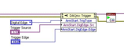
I would look at using the DAQ board for timing (internal timing). You can set up two tasks. One would be analog to measure the voltage and current. The other task would be a buffered counter measurement. You would clock it from the ai sample clock. This would give you a constant acquisition rate on the analog channel and thus give you more accurate timestamps. You would start the counter task first and then start the analog input. No triggering is required to synchronize the measurements and the measurement would be independent of whether the motor is started or not. The counter will begin counting immediately, however you can add an arm-start trigger to keep it from counting until the analog sample clock begins.
You may also be interested in reading this post. Space Flight posted this picture, which will guide you in using the above option. You will want to add the following code to the counter task to control the start of the counting:
Regards,
Jennifer O.
Message Edited by Jennifer O on 12-07-2006 06:52 PM
12-21-2006 10:48 PM
- Mark as New
- Bookmark
- Subscribe
- Mute
- Subscribe to RSS Feed
- Permalink
- Report to a Moderator
Thanks for your help. Due to time constraints, I had to go with the work around of starting the acquistion before I started the motor. That worked fine for the experiments that I was doing. I will have a look at your suggestions in the new year.
To quickly answer your first question, the digital task is required as the encoder is an absolute one which means that it provides a specific 12 bit output for each of its states. A digital input is required to capture this infomation. Unlike an incremental encoder, there is no index pulse from which to count the pulses to determine position.
Cheers
Greg
12-22-2006 09:17 AM
- Mark as New
- Bookmark
- Subscribe
- Mute
- Subscribe to RSS Feed
- Permalink
- Report to a Moderator
I am using an M series card (PCI 6259) and labview version 7.1.
I am using a 12-bit absolute encoder which comes in on port0. I have added some harware logic so that a short pulse is created each time the encoder changes. That pulse is wired to PFI0.
The goal is to take current and voltage readings (analog) and encoder reading (digital) along with a time stamp (to determine speed later) each time the encoder changes (PFI0).
Here's what I'd do:
1. Configure DI for "Change Detection" based sampling to eliminate the need for the external circuit. Specify sensitivity to both rising and falling edges on all your 12 bits. You'll need DAQmx 8.0 or later for change detection support on M-series boards.
2. When calling DAQmx Timing for the AI task and the Counter task, specify "ChangeDetectionEvent" as the source for the sample clock. You should probably start those 2 tasks before starting the DI task -- that way they'll all be ready to take a sample on the very first DI change.
3. To measure timestamps with your counter, choose the Edge Counting mode. The edges you count should be configured to use one of the board's internal timebases, like 100 kHz or 20 MHz. I don't recall for sure, but you *might* need to use a DAQmx Channel property node to specify one of these timebases as the source for the edges to count. What you'll get: a cumulative count of # cycles of a clock with a known period, i.e., a timestamp.
-Kevin P.
02-22-2007 11:40 AM
- Mark as New
- Bookmark
- Subscribe
- Mute
- Subscribe to RSS Feed
- Permalink
- Report to a Moderator
