- Subscribe to RSS Feed
- Mark Topic as New
- Mark Topic as Read
- Float this Topic for Current User
- Bookmark
- Subscribe
- Mute
- Printer Friendly Page
How to generate pulse and measure angular position simultaneously?
04-12-2007 01:15 AM
- Mark as New
- Bookmark
- Subscribe
- Mute
- Subscribe to RSS Feed
- Permalink
- Report to a Moderator
04-13-2007 12:52 PM
- Mark as New
- Bookmark
- Subscribe
- Mute
- Subscribe to RSS Feed
- Permalink
- Report to a Moderator
Is there an error code that is attached with the error message?
Causes of NI-DAQmx Error 50103 "The Specified Resource is Reserved"
Please take a look at this KnowledgeBase, is this the error that you are getting?
It is unclear what you are doing in the code and were you are doing the read/write function. With the USB-6229, there is only one ADC on the board so you are only able to run one analog input task at a time, where it will multiplex through the different channels.
Send me more information on the code and what you are trying to do, in terms of the tasks you have created in your code.
Regards,
Sandra T.
Applications Engineer | National Instruments
04-15-2007 09:57 PM
- Mark as New
- Bookmark
- Subscribe
- Mute
- Subscribe to RSS Feed
- Permalink
- Report to a Moderator
04-17-2007 12:09 AM - edited 04-17-2007 12:09 AM
- Mark as New
- Bookmark
- Subscribe
- Mute
- Subscribe to RSS Feed
- Permalink
- Report to a Moderator
It can be difficult to determine what parts of your code you are having problems with when you post a large folder with many projects and VIs in it. That being said, I am assuming that you were referring to Voltage.vi as your main program. Is that correct?
I would recommend a couple things at this point. First, I would suggest that you consider the state machine architecture for your program. This topic is discussed in more detail in this document, but basically it allows you to use LabVIEW to implement a state diagram through the use of Case structures and a While loop. This model is especially effective when you have a set sequence of steps that you would like to continuously execute (like the stepper motor). Looking at your code, you could pretty easily replace your Sequence structure with a Case structure where you determine the next case (or state) from the current case, the user inputs and the data acquired from the hardware. There are several demonstrations of state machines in the examples that come with LabVIEW, including one called "State Machine Test Sequencer.vi" which you may find useful. You can find these examples in the NI Example Finder, which you can open by clicking on Help and selecting Find Examples... Once you have the example finder open, you can use the "Search" tab to find examples on a variety of topics.
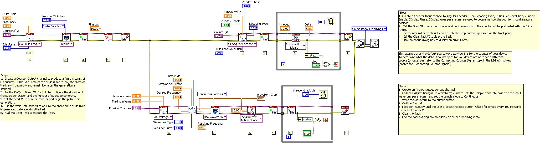
Now, in regards to your question about position measurement and pulse train generation, I have posted a VI that should help you troubleshoot this application. This VI is shown in the image below and is attached as source code. It is a combination of three example programs. These three programs perform an angular position measurement, a pulse train generation and an analog waveform generation (from top to bottom in the image). I just cut and pasted the examples together into one program and ran that. It worked on my M Series Multifunction DAQ device and it should work on your USB-6229 as well. This example program will help determine if your hardware is working correctly and should give you a good building block for your entire application. Let me know if you have any questions.

Message Edited by Matt A on 04-17-2007 12:13 AM
Matt Anderson
Hardware Services Marketing Manager
National Instruments
04-17-2007 11:24 PM
- Mark as New
- Bookmark
- Subscribe
- Mute
- Subscribe to RSS Feed
- Permalink
- Report to a Moderator
Hello Matt A.,
Thanks for your guidance. I need to generate the Finite Number of Pulses, But the VI generates the Continuous Pulses. While Change to Finite generation, the same Error 50103 "The Specified Device was Reserved" was shown by Labview. I read from online help and i am unable to solve the problem. Please give a guidance.
Thanks and regards,
Kirupasankar S
04-18-2007 11:02 AM - edited 04-18-2007 11:02 AM
- Mark as New
- Bookmark
- Subscribe
- Mute
- Subscribe to RSS Feed
- Permalink
- Report to a Moderator
I have modified the code to create a finite pulse train and posted it with this modification. Once again, all I did was cut and paste example programs together to utilize their functionality. This example is simply a combination of the examples called Measure Angular Position.vi, Gen Dig Pulse Train-Finite.vi and Cont Gen Voltage Wfm-Int Clk.vi. I would strongly recommend that you browse the NI Example Finder to become familiar with the programming structure of NI-DAQmx and the general methodology for performing DAQ.
The program I posted, as shown in the image below, does three things. First, it generates a finite digital pulse train. Then, in parallel it generates an analog voltage waveform and measures angular position using a counter. The notes in the Block Diagram should still be applicable, as I have coped them from the shipping examples as well. I have tested this code on my PCI-6251 M Series device and it runs without error. However, you are receiving the error because you are attempting to perform a finite pulse train generation in parallel with your angular position measurement. As discussed in this KnowledgeBase, the finite pulse train generation requires two counters since one acts as the gate for the other. Therefore, ctr0 and ctr1 are in use in the finite pulse train generation when you attempt to access ctr1 for the angular position measurement. You cannot simultaneously perform a finite pulse train generation and an angular position measurement (or any other counter operation) because the NI USB-6229 only has 2 counters. Both of these counters are used for the finite pulse train generation.
However, you can perform your finite pulse train generation, then clear that DAQmx task and perform other counter operations. That is what I have done in the example code and that is why it does not produce an error. Let me know if you have any questions about this example.
Message Edited by Matt A on 04-18-2007 11:04 AM
Matt Anderson
Hardware Services Marketing Manager
National Instruments
.JPG)
04-25-2007 12:58 AM
- Mark as New
- Bookmark
- Subscribe
- Mute
- Subscribe to RSS Feed
- Permalink
- Report to a Moderator
05-11-2009 06:54 AM
- Mark as New
- Bookmark
- Subscribe
- Mute
- Subscribe to RSS Feed
- Permalink
- Report to a Moderator
HI
I have:
PCI 6251M to acquire data
PCI 1427 (to acquire image with camera uniq UF1000)
Labview 8.00
Frame grabber BNC 2090
High power BI-Phase Current Simulator to generate external trigger. (ASI 701B)
In my program i need to do different things in the same time:
1)i need to reshape signal from simulator (I use lv_retirg-pulse-gen0.vi for do it ). Signal from ASI 701B is connected with pin PFI0 (input). And counter is setted on pin Counter0.
2)Read spikes from simulator and acquire data (channel's spike (ai0 is connected with output Counter 0))
3) Acquire images with my camera. Camera is connected to pin counter 1 and it need to start when spikes are generated.
I found different problem:
a)I have error 50103 on Daqmx StartTask.vi in camera line
b) if i try to resolve problem with error 50103 or camera doesn't stast but i have reshape and i can read spike
or camera starts but i cannot have reshape and i cant' read spike
or camera starts when reshape and reading spike stopped (this option it's not considerable because i need to do those operations in the same time)
Moreover i try to introduce in camera line daqmx_trigger to set trigger for start camera, using same source of counter0 (PFI0), so that camera starts when spike begin, but doesn't do what i need.
I hope you can understand what i'd like to do.
Thank for your attention
Mariangela
