- Subscribe to RSS Feed
- Mark Topic as New
- Mark Topic as Read
- Float this Topic for Current User
- Bookmark
- Subscribe
- Mute
- Printer Friendly Page
System Simulation of Analog Electronics and FPGA Control Code for Motor Control Applications
12-10-2013
04:20 PM
- last edited on
10-14-2025
01:25 PM
by
![]() Content Cleaner
Content Cleaner
- Mark as New
- Bookmark
- Subscribe
- Mute
- Subscribe to RSS Feed
- Permalink
- Report to a Moderator
National Instruments offers a new design approach for motor control applications. Designers can now simulate and optimize an entire system using system co-simulation. NI Multisim, a SPICE-based circuit design and simulation tool is used to model and analyze the power stage; NI LabVIEW is used to design the digital controller. The entire system is simulated and optimized using multi-domain co-simulation that models all the system dynamics between the analog front-end including motors and power electronics, and the FPGA graphical control code. At the end of the design stage, the code developed for simulation can be compiled to physical hardware with minor modifications.
Below is a summary of the design steps.
Analog Power Stage
The analog power stage of the design provides the interface to connect and control the DC motor. The design can be built around a common H-bridge topology (Figure 1).
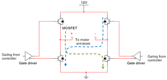
Figure 1. H-bridge topology
The DC motor is powered by a 12 V power supply. Circuit simulation in Multisim can help the designer determine whether the available power supply meets the start-up requirement. The circuit shown in Figure 2 was built and simulated in Multisim using one of the brushed DC machine SPICE models included in the Master Database. This model can be customized using the nominal motor parameters from the manufacturer’s datasheet.
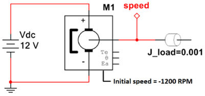
Figure 2. Circuit used to measure theoretical speed and current response
Simulation results in Multisim (Figure 3) indicate that the motor is capable of reversing from -1200 RPM to +1200 RPM in 0.51 s, however the motor experiences a large inrush current of approximately 18 A when driven hard in the opposite direction. This can be resolved by applying voltage to the armature more gradually. After extensive simulation it is determined that by applying the 12 V supply with a slew rate limit of 34 V/s, the peak inrush current can be reduced to 13.5 A. With this approach it takes 0.7 s (instead of 0.51 s) to reach the desired speed, which is still within the design requirement.

Figure 3. Theoretical speed and current responses
The switch selection for the H-bridge topology is based on the operating voltage and the maximum expected armature currents. This design features 58A N-channel MOSFETs for the low-side switch and 80A P-channel MOSFETs for the high-side. Also, a gate driver is selected for all the switches. Multisim simulation can also be used to model worst case switching losses.

Figure 4. Plant model in Multisim for co-simulation
Digital Controller Design
The digital controller is implemented in LabVIEW and consists of the following design blocks: speed decoder, PI controller, PWM Generator and H-bridge driver. Figure 5 shows a block diagram of the digital controller. All these blocks are implemented in LabVIEW, except the DC Motor (plant model) is in Multisim. Table 1 provides details about the components of the digital controller.
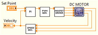
Figure 5. Digital controller diagram
Table 1. Elements of the digital controller
|
Design Block |
Description |
|
Speed decoder |
Calculates position, velocity and acceleration based on a quadrature encoder signal from the motor. |
|
PI controller |
Discretized PI controller designed to operate at a rate of 40 MHz (default clock speed for most FPGAs). |
|
PWM generator |
A PWM duty cycle of 50-100% spins the motor in the clockwise (positive) direction, while a 0-50% PWM duty cycle spins the motor in the counter-clockwise (negative) direction. |
|
H-bridge driver |
Converts the PWM duty cycle into the drive signals for the H-bridge switches. |
System Co-simulation
Now that the analog power stage and the digital controller design have been completed, the entire system can be analyzed and optimized using Multisim-LabVIEW co-simulation without the need of building a physical prototype. This reduces design iterations because errors can be detected and fixed early in the design flow. Furthermore, the LabVIEW code created for the system simulation can be reused and implemented in hardware with minimal changes.
In the co-simulation environment, the Multisim and LabVIEW simulation engines concurrently perform a non linear time-domain analysis, exchanging data at the end of each time-step. This means the simulation results are accurate because all the system dynamics is taken into consideration. The LabVIEW block diagram for the system simulation is shown in Figure 6.
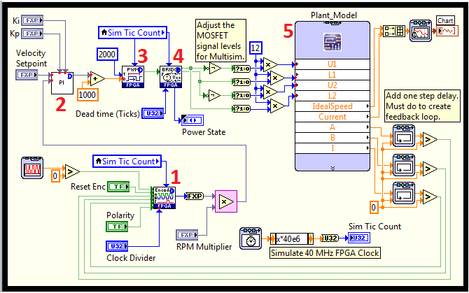
Figure 6. Closed loop system simulation in LabVIEW
From the previous figure you can see that nodes 1-4 are elements of the digital controller:
- Speed decoder
- PI controller
- PWM generator
- H-bridge driver
The plant model, represented by node 5, consists of the MOSFET switches, brushed DC motor, and an optical encoder executing in the Multisim simulation environment.
Figure 7 features a 1 s simulation of the system setting the motor speed from stopping to 1200 RPM. In the graph, the setting speed is represented by the red trace. The yellow trace depicts the simulated sensed speed. These results show that the design meets the application requirements.
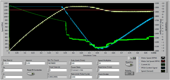
Figure 7. Co-simulation results
With Multisim and LabVIEW co-simulation designers can also evaluate current peaks and control signals, assess the efficiency of speed encoding/decoding and predict the transient time response of the motor speed build-up.
