- Subscribe to RSS Feed
- Mark Topic as New
- Mark Topic as Read
- Float this Topic for Current User
- Bookmark
- Subscribe
- Mute
- Printer Friendly Page
Problem on MRCC/SRCC clock in function(source sync communication issue)
11-30-2015 09:18 AM
- Mark as New
- Bookmark
- Subscribe
- Mute
- Subscribe to RSS Feed
- Permalink
- Report to a Moderator
Dear All:
I was trying to use fpga to connect to a highspeed adc, running at about 100M, and I'd like to use the built-in clock function to trig data read out.
Because if I read out the data from adc with my on clock, I will have to over-sampling the input clock at least of 2 times of real adc sample clock, I can use the clock generate loop as read out time base, but it wouldn't provide much margin of error if the system parameter changes slitly.
The ADC itself already provided a clockout pin, and can be adjust at 8 different phase, which is very handy if I can use this clock to trig my read out code, but at there I met a problem.
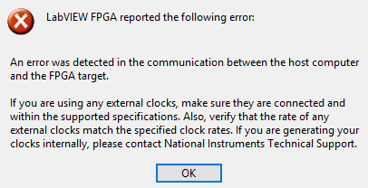
The code can compilation, but eventime I try to run the code, it says I don't have a input at some clock in port. which is true since I will have my FPGA running then I will have clock exported to ADC, and after data is convented, ADC will provide clock back to FPGA.
11-30-2015 11:43 AM
- Mark as New
- Bookmark
- Subscribe
- Mute
- Subscribe to RSS Feed
- Permalink
- Report to a Moderator
Hi Jiangliang,
Can you confirm your connections and clock pins in the LabVIEW code?
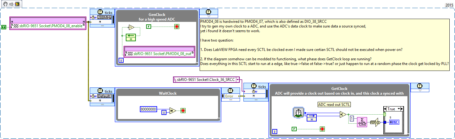
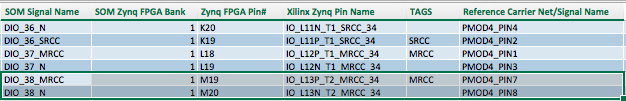
In your screenshot, you mention that you have wired a jumper from PMOD4_PIN8 to PMOD4_PIN7. PMOD4_PIN7 is "DIO_38_MRCC" but it appears the pin used for the clock in the GetClock loop is "DIO_36_SRCC". I'm afraid you may have crossed DIO_36 and DIO_38 unintentionally in software, as both pins are clock capable and similarly named.
In gereral, I don't believe the external CLIP clock has to be glitch free or continuously running, but your code must be able to deal with those issues. I'm not sure if additional constraints are applied when that CLIP clock is routed to the LabVIEW FPGA diagram. I'm hoping someone on my team can add a more definitive reply, but I wanted to post as quickly as I could to point out the potential wiring issue.
http://zone.ni.com/reference/en-XX/help/371599K-01/lvfpgaconcepts/create_acq_clip/
Regards,
spex
National Instruments
To the pessimist, the glass is half empty; to the optimist, the glass is half full; to the engineer, the glass
11-30-2015 12:12 PM
- Mark as New
- Bookmark
- Subscribe
- Mute
- Subscribe to RSS Feed
- Permalink
- Report to a Moderator
I believe that imported clocks must be running when the diagram starts up, otherwise you will see that error. I recommend that you keep all clocks running at all times.
It looks like you are importing a clock correctly, but it looks like you are exporting a clock incorrectly.
You say that you want a clock that is running around 100MHz. In your diagram, it looks like you created a clock divider circuit with a register that takes a 288MHz signal and divides it down to 144MHz and you send the signal into the CLIP. LV FPGA and the synthesis tools handle clock signals and data signals differently, so I recommend that you export your clock signal as a clock instead of a data signal.
If you would like to create a 144MHz clock from a 288MHz clock, I recommend that you right-click a clock you would like to derive from and click "New derived clock". This will instantiate an MMCM in your diagram logic and produce a clock signal and LV FPGA and the synthesis tools will handle correctly. Xilinx MMCM's will produce a higher quality clock signal and will include your clock signal in it's timing constraints.
If you would like to export a clock in your LV FPGA project to a CLIP, use the sbRIO CLIP Generator to add a ToCLIP clock. It looks like you already added a FromCLIP clock named Clock_36_SRCC. The process is very similar, just assign it to go the other direction. Exporting clocks do not need to use clock capable pins. The socket property page has a page about clocks. From there you can choose which clock from your project to assign to the CLIP. If there is a clock in your project that meets the requirements defined in your CLIP, then I believe it automically assigns it.
I would do a clock loopback test to see if everything is working correctly. Connect your exported clock to your imported clock and make sure that works correctly. If that is working properly, then you can try putting the ADC between the two clocks and check to see if it still runs correctly.
11-30-2015 03:56 PM
- Mark as New
- Bookmark
- Subscribe
- Mute
- Subscribe to RSS Feed
- Permalink
- Report to a Moderator
Jianglang,
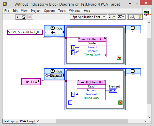
To add a little to what Spex was saying, the external CLIP clock doesn't have to be glitch free or continuously running, the specific reason that error is being thrown is that you have an indicator inside that single-cycle timed loop. When you run the code interactively, LabVIEW is trying to read all indicators and since that one's in code that hasn't executed yet, it throws that error. If you don't run the code interactively, and only read that indicator once the clock has started you shouldn't see that error, additionally if you replace the indicator with something like a FIFO (see below) the error won't be thrown as well.
Bryan
11-30-2015 08:18 PM
- Mark as New
- Bookmark
- Subscribe
- Mute
- Subscribe to RSS Feed
- Permalink
- Report to a Moderator
Thank you very much, I'll try if it works when I get back to my office.
11-30-2015 11:49 PM
- Mark as New
- Bookmark
- Subscribe
- Mute
- Subscribe to RSS Feed
- Permalink
- Report to a Moderator
Hi nturley:
I was not able to found how to generate a "New derived clock", I only can generate new clock based on 40MHz on board clock, can you kindly tell me about how to setup a new derived clock based my custom clock? Thanks.
------------------------------------------------
update:
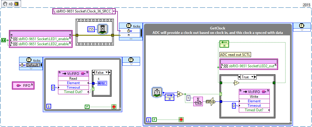
I already found how to make new derived clock based on external clock. but still, I have problem running a external clocked SCTL, please take a look at the picture I attached next post. Thank you~
----------------------------------------------------
update 2:
I successful get system running at the external clock, thank you!
One thing I would like to know is if I export clock via a none MRCC/SRCC pin, would the clock became somewhat degraded? Thanks!
12-01-2015 02:30 AM
- Mark as New
- Bookmark
- Subscribe
- Mute
- Subscribe to RSS Feed
- Permalink
- Report to a Moderator
Hi Deagle:
I did as you suggested, program niw runs without error, but the inductor is
not counting, I added a led to see if this loop actually runs, it doesn't.
I double checked the connection, I made pmod 4 pin2 connected to pmod4 pin8, and made sure there are clock running at both pin.
In the clip configure, I checked bank 0,1 is 3.3V, and bank2,3 is 1.8v, and clock range is 5~200MHz.
Can you help me with any suggestion? Thanks!
Attachment is the new diagram, when I run the vi, only one led blinks...
----------------------------------------------------------------------
update:
I did as nturley suggested, I set DIO 38_N as a "To CLIP clock", and I set the clock to 96M, and connected to DIO_36_SRCC, the loop can clock itself now, but at a wrong speed, it seems runs at 200MHz(according to the S indictor, I set timer to 8bit ms counter, and after 256ms I reset counter once, I got s of 51200000, which means cycle runs at 200M), but according to LED state, it not running at all, the LED should blink at 256ms, but nothing happens to LED.
Do you have any idea about this issue?
12-01-2015 06:18 AM
- Mark as New
- Bookmark
- Subscribe
- Mute
- Subscribe to RSS Feed
- Permalink
- Report to a Moderator
Thank you, Spex.
I have checked my connection, and measured there are clocked signal in the pin I use.
I'm now connected PMOD4_2 and PMOD4_8, and set PMOD4_8 as a TO Clip clock. Which is DIO_36_SRCC and DIO_38_N respectively.
The thing is I can ran the program which out error promote now, thanks to Deagle, but the actual loop is not running, and the result gives me confilcting results:
My counter in the externally clocked SCTL says the loop runs at 200Mhz, and my LED flipping code says the loop is not running at all.
I'm really confused now, please give me some advice, thank you!
12-01-2015 07:53 AM
- Mark as New
- Bookmark
- Subscribe
- Mute
- Subscribe to RSS Feed
- Permalink
- Report to a Moderator
Hi All:
I might found the problem: I should not use mSec as tick count units, when I change it to ticks, I can see the LED output changes.

But there is one more question I have:
Which Edge does the SCTL runs? The rising edge or the falling edge? Can I configure it somehow?
Thank you all for your help~
12-01-2015 10:43 AM
- Mark as New
- Bookmark
- Subscribe
- Mute
- Subscribe to RSS Feed
- Permalink
- Report to a Moderator
Glad everything is working. 
As far as I know you should be able to export a clock from any pin. The MRCC/SRCC pins allow lower latency access to the clock distribution network in the FPGA, but for exporting a clock, it shouldn't make a difference. As long as the clock signal is being driven directly by a clock manager instead of being gated or registered.
I think all data is registered every rising edge.
