- Subscribe to RSS Feed
- Mark Topic as New
- Mark Topic as Read
- Float this Topic for Current User
- Bookmark
- Subscribe
- Mute
- Printer Friendly Page
Clip node synchronization
08-31-2015 02:29 AM
- Mark as New
- Bookmark
- Subscribe
- Mute
- Subscribe to RSS Feed
- Permalink
- Report to a Moderator
Hi guys,
I generated a clip in my project for a SPI communication. I would like the exit node ( so a I32 which contain the spi word) to time the loop.
So today, we have an ADC which run to 51k and our while loop run faster, then we have multiple time the same data.
How synchronise our clip node to block the loop until the new data isn't available( Like the cRio module).
Thanks
08-31-2015 12:00 PM
- Mark as New
- Bookmark
- Subscribe
- Mute
- Subscribe to RSS Feed
- Permalink
- Report to a Moderator
MMO832,
I do not think you can read the SPI faster than the data arrives. It could be your code implementation. You should wait for line transistions to 'clock' to that data.
This would be a shift-register in the loop that compares the line level to the previous loop iteration - if it's NOT equal AND TRUE, you have new data. Don't try to read the lines states wide open in the loop.
I don't think you even need a timed loop at all. I've done I2S which is similiar with 24kHz ADC data and it works fine, infact the loop does not operate until the ADC startes to send.
There should be example code for this on the forums.
Take a look at your code....
Regards
Jack Hamilton
08-31-2015 12:43 PM
- Mark as New
- Bookmark
- Subscribe
- Mute
- Subscribe to RSS Feed
- Permalink
- Report to a Moderator
MMO832,
If your ADC provides any sort of signal that a convert is done you can use a while loop to block on that assertion. This will allow your code to only finish running until the value has been asserted and given yourself a chance to read the value.
The other option is handling requrests on a timed interval, Any requests received will only be fulfilled on the next available sample time.
Senior Embedded Software Engineer

09-01-2015 01:55 AM
- Mark as New
- Bookmark
- Subscribe
- Mute
- Subscribe to RSS Feed
- Permalink
- Report to a Moderator
Hi guys,
Thank you for your feedback, but I was bit confusing in my explanation.
Your solutions respond to my problem but it force me to have an other node to define if a new data is available ( like a data ready).
Just to be clear, I just want mimic the analog I/O node from Cserie module (9232, 9234) which time the loop by itself. Is it possible?
Regards,
MMO832
09-01-2015 11:39 AM
- Mark as New
- Bookmark
- Subscribe
- Mute
- Subscribe to RSS Feed
- Permalink
- Report to a Moderator
MMO832,
This is what we essentially do under the hood. You can either wait long enough to ensure you have new data or wait for a signal to assert data is valid.
We do this behind the scenes of the IO nodes that you add to the block diagram.
Senior Embedded Software Engineer
09-01-2015 02:30 PM
- Mark as New
- Bookmark
- Subscribe
- Mute
- Subscribe to RSS Feed
- Permalink
- Report to a Moderator
You could also encode the data valid flag in the binary of the IO node if the number of IO nodes exposed in the project is what you are trying to minimize. For example, you could add a 33rd-bit that asserts when data is valid and your FPGA VI can look for a data change accompanied by the data valid flag to determine when data is both new and valid.
-spex
National Instruments
To the pessimist, the glass is half empty; to the optimist, the glass is half full; to the engineer, the glass
09-02-2015 03:01 AM
- Mark as New
- Bookmark
- Subscribe
- Mute
- Subscribe to RSS Feed
- Permalink
- Report to a Moderator
So the modifications necessary to make a blocking node aren't available for me.
There are no options to modify in xml, vhdl or in the node in labview to enable this function.
"This is what we essentially do under the hood", I understand that it's possible but the modifications aren't reachable by myself. So, it's necessary for me, to create a flag that I manage in Labview ( solution of other node or 33rd bit).
Do you confirm?
09-02-2015 02:16 PM
- Mark as New
- Bookmark
- Subscribe
- Mute
- Subscribe to RSS Feed
- Permalink
- Report to a Moderator
CLIPS run in parallel to the fpga block diagram so you'll need to implement a mechanism to tell LabVIEW FPGA the data is valid. If you see section 4 that describes the behavior differences between CLIPs and IP Integration Node.
http://www.ni.com/tutorial/7444/en/
Senior Embedded Software Engineer
09-04-2015 05:06 PM
- Mark as New
- Bookmark
- Subscribe
- Mute
- Subscribe to RSS Feed
- Permalink
- Report to a Moderator
Hi MMO832,
I threw together a quick example of what I believe could work for your situation. You stated that you would like a blocking call, similar to what we have with our I/O nodes that correspond to C Series modules and if we have any internal hooks or XML file changes to enable a CLIP node or other block diagram component to block until data is ready.
We do not have any internal hooks or XML changes as LabVIEW does not know when your data will be valid from your ADC; In other words, there is no XML tag to set 'blocking' to true. You, as the developer, are responsible for knowing when the data will be valid. As mentioned earlier, having a data valid bit or signal from the ADC can be leveraged to achieve the behavior that you require, although it will not look exactly like a C Series I/O node, but it will provide the same behavior.
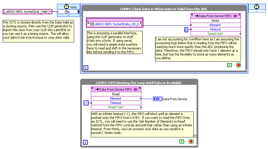
In my example, I used the sbRIO CLIP Generator to combine 8 single-ended signals and bring them into LabVIEW as a U8. I also imported a clock into LabVIEW that represents a Data Valid signal. Through the CLIP Generator's user interface, you can only import a pin from the SOM's connector as an external clock source. If you do not have a Data Valid pin on your ADC, you can also modify the CLIP VHDL and XML to perform some additional Data Valid logic and use the output signal of that to be imported into LabVIEW. Of course, this is assuming that the data is always valid when Data Valid asserts.
One of the many great features of the SOM and the newly-released sbRIOs is the ability to use an imported signal as a clock source for a Single-Cycle Timed Loop (SCTL). In my example, I am using the Data Valid pin from an imaginary ADC to clock the data of a parallel interface into a Target-Scoped FIFO. This ensures the data being read from the CLIP node is valid as it is synchronous to Data Valid. This is the first important thing to note about the example.
The second important note about this example is in the lower loop. I have the other end of the FIFO set with an infinit timeout. In a While Loop, this means that the FIFO Read Method will block for an infinite amount of time until the upper loop pushes an element of data into the FIFO. As long as your consumer loop is being clocked faster than the producer loop, the FIFO should always be underflowing and have ~1 element or less. The great thing about FIFOs are that if the producer loop is sending bursts of data, the FIFO will not be lossy as long as it has a sufficient number of elements. For your case, the upper loop will likely be clocking data in at a consistent rate so make sure it will be slower than consumer loop. Having an infinite timeout on the FIFO means you have a the same effect as a C Series I/O node would. The block diagram element is a FIFO so you could wrap it in a subVI to give your API a more custom look.
If you are instead operating the consumer loop as an SCTL rather than a While Loop, you will need to peek at the FIFO and see if there is one or more elements before actually reading it. This is because SCTLs require a FIFO timeout of zero.
Alternative Approach:
A potentially more intuitive and LabVIEW-centric way of solving this is to import both the Data_U8_in and Dat_Valid signals as a CLIP node. You could then read these values in an SCTL that is sufficiently fast to always catch the Dat_Valid edge. You could then implement and edge detector that only pushes data into the FIFO on a rising edge of Dat_Valid. This shouldn't be a problem at lower speeds but if you are sampling much faster, it may be difficult to generate a sufficiently fast SCTL clock to ensure that you are always catching a Data Valid edge.
National Instruments
09-04-2015 05:14 PM
- Mark as New
- Bookmark
- Subscribe
- Mute
- Subscribe to RSS Feed
- Permalink
- Report to a Moderator
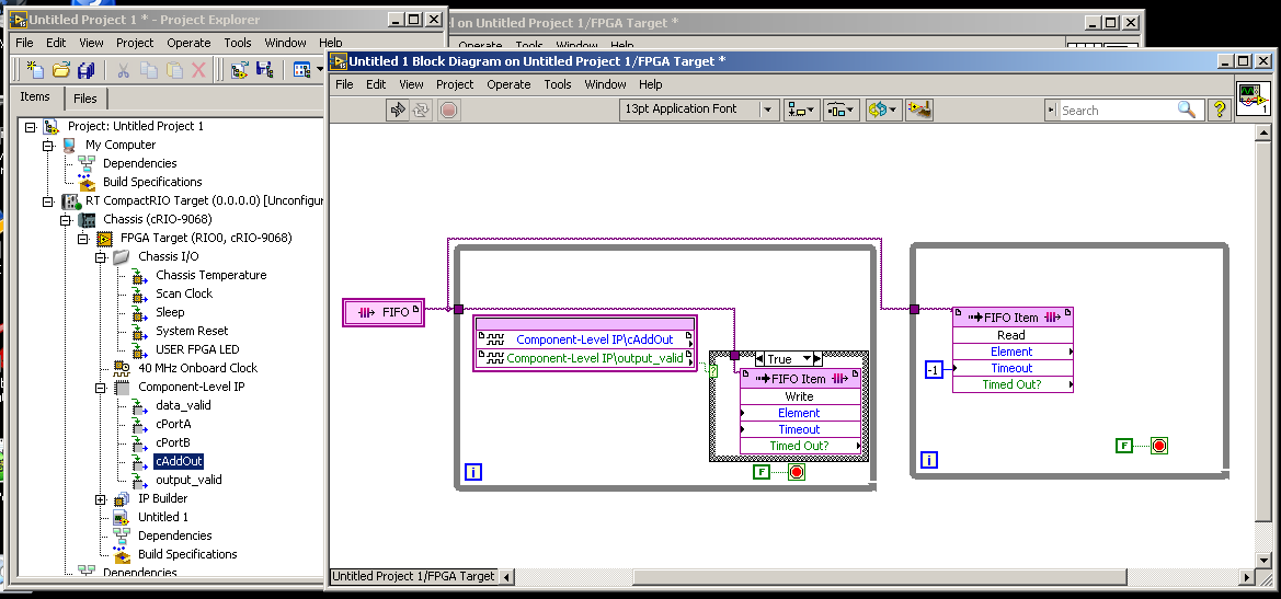
Here are the two examples described above using the same vhd code. It is not fully tested for glitches but you can use this as a guide to synchronize data between CLIPs and the FPGA block diagram. This is not taken from a specific module and this should not be a guage for how the actual code was written for IO nodes.
The first is providing a clock signal to trigger when samples are fresh. In the screen shot we can use a Timed loop to import this clock so the loop only executes with the clock ticks. I've simply imported my data valid line as a clock. This way the loop is blocking on the actual data.
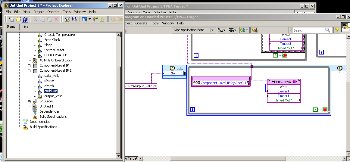
If you choose to only use the data valid flag as a boolean you can use a similar structure to read the data and push it to a fifo for analysis later.
For more complicated clips it may be necessary to implement 4 wire handshaking where LabVIEW in the clip each signal when data is ready as well as verifing that data has been clocked in.
Senior Embedded Software Engineer
