DAQmx Analog triggering by software under LabWindows CVI
- Subscribe to RSS Feed
- Mark as New
- Mark as Read
- Bookmark
- Subscribe
- Printer Friendly Page
- Report to a Moderator
Code and Documents
Attachment
Overview
When acquiring signals, it could be useful, depending of the application, to launch the data processing only once a signal reachs a predefined threshold. If the NI DAQ hardware you own does not support the 'analog triggering' ability you can overcome with that thanks to a piece of software. This paper deals with a method for managing pre and post triggering written under NI LabWindows CVI.
Method
1/ It is supposed that the total acquisition duration T is known (for example you need 1s of data)
2/ The channel (among two) for the triggering is choosen (for example the tension measured on the channel 1)
3/ The threshold Vt of triggering is choosen (here 1V -- tension could range between 0 and 5V according to the configuration)
4/ An 'hysteresis' coefficient h is defined so that the data processing is triggered when the signal 1 is growing from Vt/h to Vt.h (for instance h=1.01).
5/ The total duration of the relevant acquisition is divided in N blocks of data (for example N=10)
6/ The amount of data in one block is equal to T/N*rate*2*sizeof(double) (for instance (1s/10) x 10,000Hz x 2 x 8 bytes = 16,000 bytes)
7/ The N blocks take place in a circular buffer : 0 1 2 3 ... N-1 which size is N times the size of one block.
8/ The acquisition is continuous and the DAQ acquires 1 block by cycle - An index caracterizes the number of the next block to acquire. Therefore, this index always point out the first block given that the actual acquired block is the last by definition. The index is incremented by one (modulo N) after each block acquisition. The data of the two channels are interleaved so that they can be optionnaly displayed in a strip chart.
9/ After a block is acquired, the software look into the second block (just after the first block) if the signal has rised from Vt/h to Vt.h. If yes, the data can be processed and, temporarily, the triggering is suspended but the measures continue)
10/ In this example, the processing consists in a displaying of both the channels onto a graph. For that the data buffer is submitted to two consecutive transformations : (a) the logical first block must take the first physical place in the buffer. For that a rotation of the buffer is proceeded. For instance if the blocks are found to be ordered as 5678901234 (in case of 10 blocks) the rotation will give 0123456789. (b) The interleaved data are separated such enabling the plotting or any further treatment (FFT for instance). The sequences ABABABABABABAB.......... are converted in AAAAAAAA.....BBBBBBBB.........
10/ An other triggering can be rearmed thanks a command button which raises a flag managed by the collect callback.
Program
The program UTTrigger is provided as an example of the method described above. It is written in one file. Obviously an uir file is associated.
The constants
NBLOCKS is the number of blocks
BLOCKSAMPLES if the number of samples per bloc (one sample contains the measures on the two channels)
NBCHANNELS (here 2) is the number of channels managed by the daq device
RATE (here 1E4) if the rate in samples per second (whatever is the number of channels)
TIMEOUT is required by DAQmx
THRESHOLD is the value which triggers the data processing (here 1.0V)
HYSTFACTOR if the hysteresis factor (1+1% therfore 1.01)
The global variables
daqerr is the number of the last DAQmx error (managed by the macro DAQmxErrChk and the function DAQmxErrProcess given in the C-source)
block0 if the index of the first block in the buffer (and therefore the next to be acquired)
daqData if the address of the entire buffer (containing NBLOCKS blocks)
dt is the time resolution (expressed in ms) therefore is equal to the ratio 1000ms/RATE (here 1000/10 kHz = 0.1ms) - the duration of a entire buffer acquisition lasts NBLOCKS x BLOCKSAMPLES x dt = 10 X 1000 x 0.1 ms = 1.0 s in the present case.
flagtrigger is a flag which raises after a trigger is detected. The uir interface offers a [RUN] button for rearming the detection.
The static functions
GroupDataPerChannel
Separate the interleaved channels in two separate zones. Operates onto the buffer pointed by daqData.
RotateCircularData
Rotates the buffer so that the first logical bloc takes the first physical place in memory.
DAQmxStop
Stop the acquisition (when the program ends).
DAQmxStart
Launches the aquisition (when the program starts).
DAQmxConfig
Configures the acquisition task :
- create the task
- configure the two channels (tensions between 0 and 5.0V in the present case) - the program was tested with a simple NI USB6002)
- configures the hard triggering : internal clock for continuous acquisition of blocks
- register the callback which is activated when a block if full
DAQmxErrProcess
Displays the error message of the library DAQmx in a popup and stop the operations.
The main function
Initializes and displays the uir panel. Runs the interface.
DAQmx callback
One callback only:
DAQEveryNCallback
a/ Allocates memory for the buffer at the first call.
b/ Reads the data block
c/ Plots the data in the stripchart
d/ Update the logical block index (incrementation modulo NBLOCKS)
e/ Looks for the trigger in the logical block 1. This action is only done if the flag flagtrigger is down: check if, in the block 1, the signal (channel 1) raises from threshold/h to threshold*h. If yes, rotate the buffer, separate the channel data and displays both the channels in a graph control. Raises the flagtrigger.
UIR Callbacks
QuitCallback
As usually. Stop the acquisitions and the user interface then quits.
RunCallback
This callback is acivated by a push on a [RUNBUTTON] command button on the panel.
At the first call: configures and starts the analog acquisitions. Deletes the graphs. Clears the buffer. Restores the block index to zero. Downs the flagtrigger thus enabling a new sequence of triggering.
Operations
hardware
- connect a DAQ device to your computer (example NI USB-6002)
- connect two tensions sources (range 0 to 5V) tunable thanks a potentiometer
- check that the hardware operates with the NI Measurement & Automation Explorer
software
- downloads the files (UTTriger.c and UTTriger.uir at minimum).
- check for the hard-encoded parameters (channels configuration).
- rebuild the executable thanks LabWindows CVI (needs DAQmx library and the drivers of your DAQ device installed).
- run the program. The acquisition starts immediately.
- change the signal on channel 1. If it raises accross the trigger threshold, the graph of the buffer (two channels) is displayed. The acquisition is not interrupted.
- for relaunching the process press the [RUN] button.
Conclusion
This program ensures that the trigger value is always embedded in the logical bloc 1 (the second one). Therefore the buffer always begins by one block before the trigger: the function of pretriggering is provided. Moreover the buffer includes NBLOCKS-2 blocks after the block containing the trigger (post triggering is provided as well).
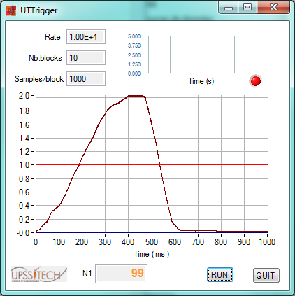
FIGURE: The UTTrigger interface. Top-righ: the stripchart (signals are low). The acquisisition is continuous. Middle: the graph (signal 1 only). The threshold is figured by the red line. Thanks the algorithm, the threshold always belongs to the block 1 (between 100 and 200 ms when the signal is rising). Bottom-right: the button [RUN] re-arms the process. Bottom-center : counter of the block acquisitions.
The program is just provided as an example of the general method which could be adapted to any data collection requiring triggering and when the available device does not support this option. In case the process stage is too long, the program could be organised in two threads.
The technique presented here was developed for acquiring dynamic signals from a model of a structure for academic purpose. Signal 1 came from an impact hammer and signal 2 from an accelerometer. the management of both the signals is launched by a threshold according to the hammer impulsion. The full data process (out of the scope of this paper) leads to the frequency response function of the frame.
Example code from the Example Code Exchange in the NI Community is licensed with the MIT license.
