Overview
This example introduces the myDAQ PCB connector.
Description
The myDAQ PCB connector can be used to design and make custom PCB boards that can plug in myDAQ. The miniSystems use this part in its every design for myDAQ integration.
Requirements
NI Multisim 11 or compatible
NI Ultiboard 11 or compatible
Connector Availability:
The NI myDAQ 20 pin PCB mountable connector is available at $50 for quantity 25 by calling NI at 1-800-433-3488.
Use part number 781334-01 NI MYDAQ ACCESSORIES: 25 PCB MOUNTABLE CONNECTORS
Merging Database:
To add the PCB connector to your Multisim/Ultiboard Database, in Multisim go to Tools > Database > Merge Database. Select the corporate database attached and continue from there. The component will be in your Corporate Database, under NI_Connectors. Also check the video attached.
Some points to note:
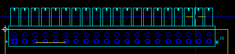
- As you can see in the footprint once you open it, the vector of pins that are dimmed are "unconnected" and always will be. These are only for mechanical support and are short-circuited to the pair next to it internally in the physical connector, they should be soldered when producing the board.
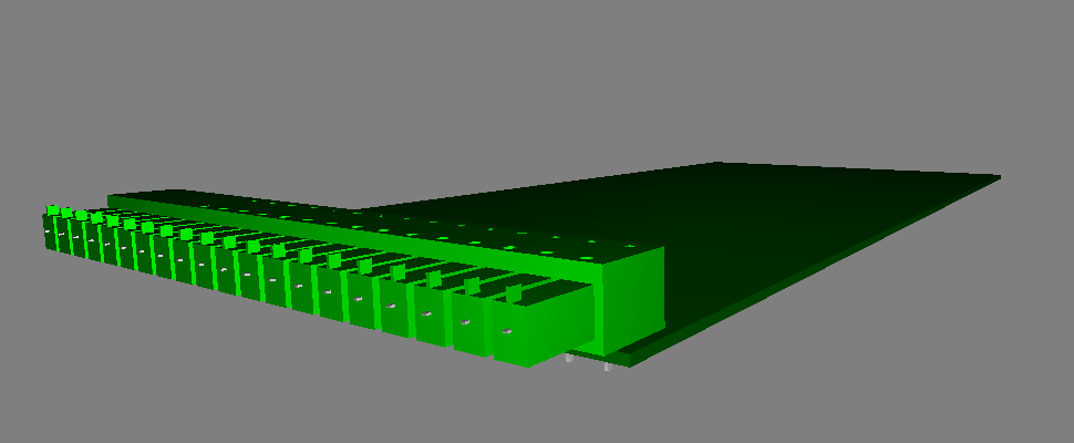
- The silkscreen line parallel to the unconnected vector of pins must be aligned with the board outline. The male pins will be inserted in the matting header located in the myDAQ device so you have to account for that space "off the board outline". Find attached an Ultiboard file to see how you should align it. Also reference the 3D representation below.
- Be careful to consider that on the left-side of the myDAQ device header, there are two other connectors (audio input/output), so be aware of this when deciding the shape of the board outline and the location of the myDAQ connector. That is why in the Ultiboard file, it is placed it next to the edge of the board outline.
Please find attached:
- Database file
- Multisim and Ultiboard files for reference.
- OST connector datasheet for reference.
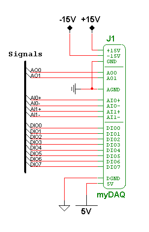
Multisim Schematic Representation:
Ultiboard Schematic Representation:
3D Representation:
**This document has been updated to meet the current required format for the NI Code Exchange.**
