Switched VNA Reference Architecture
- Subscribe to RSS Feed
- Mark as New
- Mark as Read
- Bookmark
- Subscribe
- Printer Friendly Page
- Report to a Moderator
Code and Documents
Attachment
Overview
This reference architecture serves to demonstrate the use of NI PXI VNAs with NI PXI switches for multi-port measurements.
Description
VNAs are often used in conjunction with switches to increase their total number of ports. This reference architecture should be used as a foundation for beginning switch-based VNA measurements as it incorporates many important practices for robust, reusable, and scalable applications. Many components have been optimized for performance, notably measurement time per port tested.
Because of the sensitive nature of VNA measurements, care must be taken to separately calibrate every switch path (typically one per UUT socket) to compensate for factors such as switch cross-talk, isolation, and insertion loss, which are unique to each path. Once calibration data is obtained for every UUT socket, it must be applied to the raw uncorrected measurement data in correlation with each corresponding switch path. Loading new correction factors onto an instrument each time the switch path changes adds unnecessary test time (2-3 seconds per commit), slowing down overall throughput. Since this instrument loading dominates an overwhelming majority of the total test time, improving this aspect has drastic performance implications for multi-UUT applications.
To decrease this test time, we can leverage the software-defined advantage of PXI by configuring the VNA to return uncorrected data. Identical sweeps are performed across all UUT sockets and system vector error correction is applied in software post-acquisition without having to re-commit any settings to the VNA between sweeps. This way, we avoid the performance hit taken from loading new correction factors for each UUT socket. The more ports being used, the more you benefit from this optimization.
Please note: Current support is only implemented for reflection measurements on VNA port 1.
Execution Flow
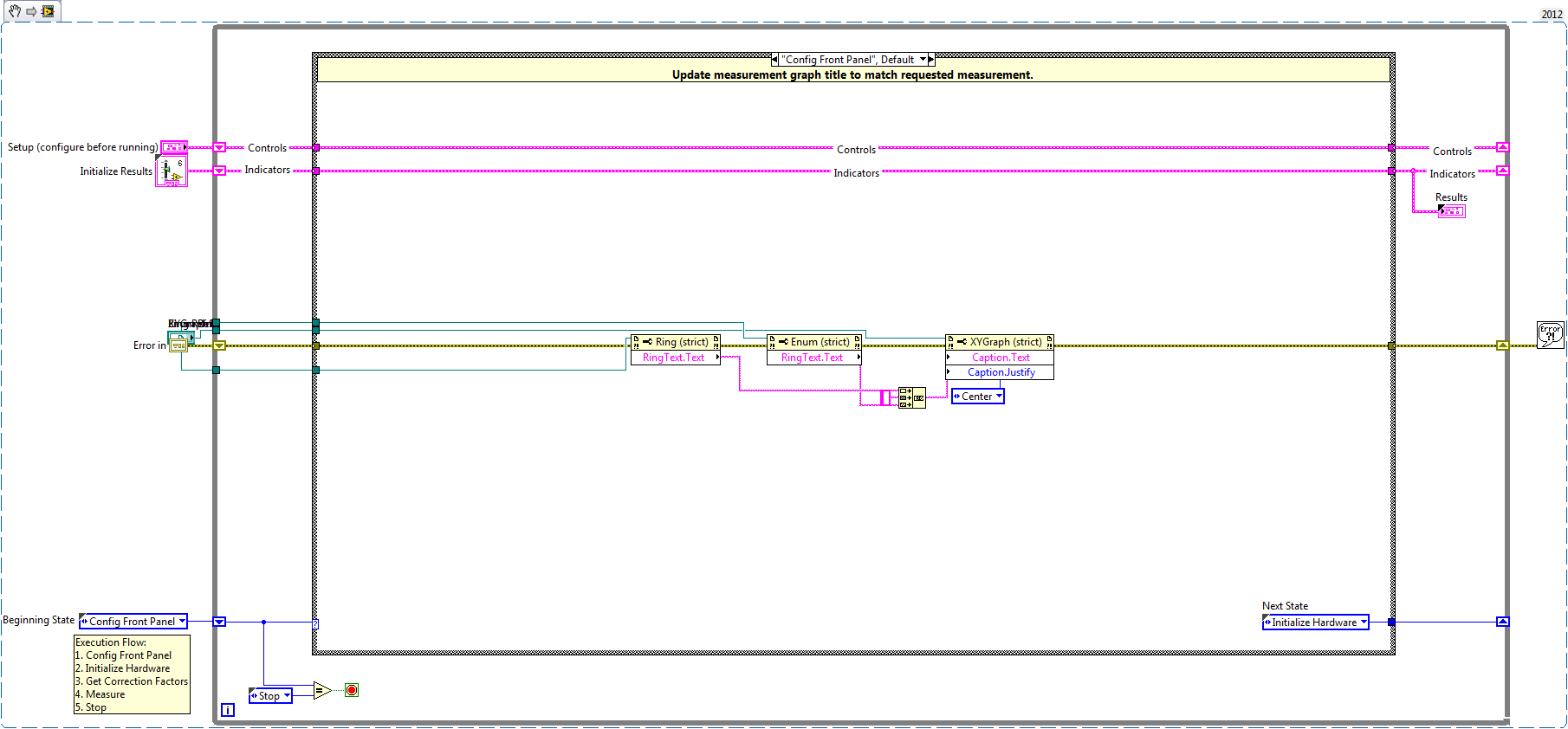
- Config Front Panel
- Update measurement graph title to match requested measurement.
- Initialize Hardware
- Start VNA session. Switch session is not opened here because it is handled by "Switch Control.vi" in the "Measurement" case.
- Get Correction Factors
- Load the calibration file for each switch path and extract correction factors so that measurements can be performed without having to reload calibration files between sweeps.
- Note: This step only needs to be called once if calibration does not change
- Configure VNA
- Configure VNA for switched measurement and update Front Panel to display sweep settings.
- Measure
Relay control
This subVI sets your switch path for the current measurement.
Note: Edit this subVI to support your switch setup. Current support is for 2597 and 2543 RF switches.
Initiate sweep, wait for finish, and fetch measurement
Perform a single sweep for one switch path. Then get the current measurement data from the VNA after the sweep is complete.
Note: The VNA should be configured to return uncorrected data.
Perform error correction and format data
This subVI uses the correction factors associated with the current switch path to apply vector error correction to the measurement data. Corrected data is then formatted for display according to user selection.
Update measurement data
Add current measurement data to results for display.
- Stop
This execution flow can be modified such that the Get Correction Factors step is only called once, after which the Measurement step can be repeated for multi-batch systems (user prompt may be required to pause execution while DUTs are swapped in/out). This is the key where test time improves, because subsequent measurements do not require committing any settings to the VNA, even when changing switch paths with different correction factors.
Steps to Implement or Execute Code
- After loading the project, open "Switched VNA Main.vi"
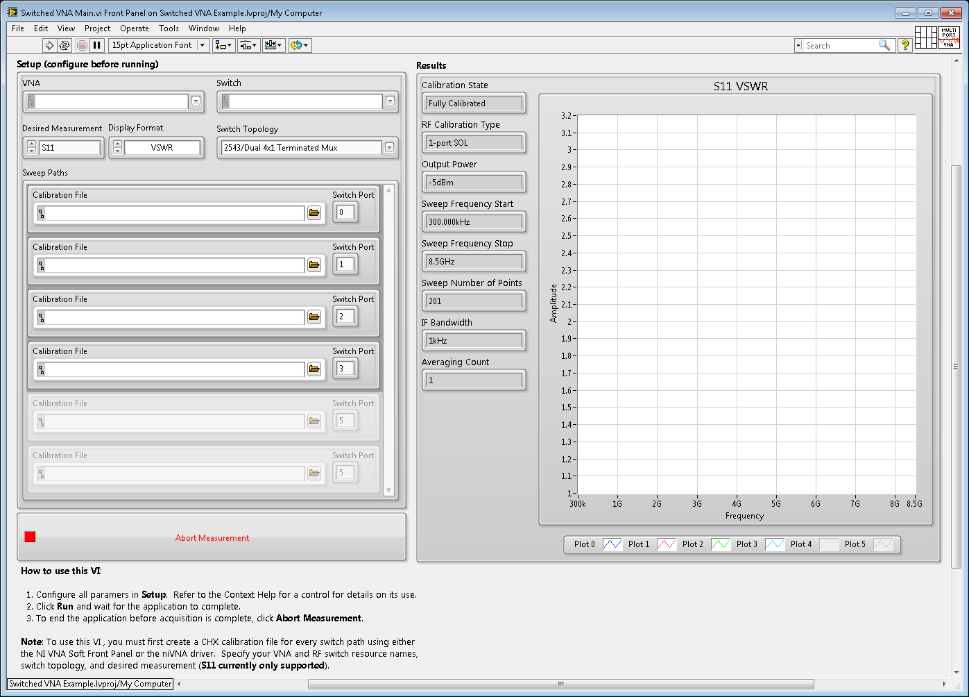
- Configure the Front Panel controls according to the documentation.
- Run the VI.
Requirements
Software
- LabVIEW 2012 or later
- NI-VNA 2.0.1 or later
- NI-SWITCH 4.6.5 or later
Hardware
- NI PXIe-5630 or NI-PXIe-5632
- NI PXI-2597, NI PXI-2543, or NI PXIe-2543
Future Release Plans
- Producer/Consumer architecture to de-couple configuration and measurements from analysis
- Error checking code to validate switch path selections are supported by the switch topology
- Support for the use of additional switches
- Multi-bank switch support
- Reflection Measurements - Allow simultaneous use of port 1 and port 2 on multi-bank switches for parallel S11 and S22 measurements
- Transmission measurements
Support
- Switched VNA Reference Architecture - Bug Reports
- Switched VNA Reference Architecture - Feature Requests
Additional Images
Front Panel
Block Diagram Snippet
Chris Elliott
x36772
Example code from the Example Code Exchange in the NI Community is licensed with the MIT license.
- Mark as Read
- Mark as New
- Bookmark
- Permalink
- Report to a Moderator
Hi
As there are two method for large signal measurement systems: The sampler-based technique and the mixed-based approach.
Sampler based technique is used in LSNA and mixed-based approach in NVNA.
Kindly correct me If I am wrong, I am new to this field.
Is there any application notes from where I can understand the working of both so that I can better understand.
Thanks.....
- Mark as Read
- Mark as New
- Bookmark
- Permalink
- Report to a Moderator
Hi gctripathi,
This example is for general purpose VNA. Switching in this case is to increase the total number of ports for reflection measurements.
For general questions, our RF Academy would be a good starting point to learn about fundamental RF concepts. While it may not contain specific information regarding LSNA and NVNA, it is continuously updated and I would suggest looking out for new content.
Julia P.
Applications Engineer
National Instruments
