R Series Only Multi-Axis Motion
- Subscribe to RSS Feed
- Mark as New
- Mark as Read
- Bookmark
- Subscribe
- Printer Friendly Page
- Report to a Moderator
Products and Environment
This section reflects the products and operating system used to create the example.To download NI software, including the products shown below, visit ni.com/downloads.
- PXI-7852
Hardware
Code and Documents
Attachment
Description
Description-Separate-1There has been some recent interest in being able to perform multi-axis motion with an R Series card without the need for a Real-Time component. This example was designed to do exactly this, Windows and FPGA only multi-axis motion control. The advantage to this is that the system architecture is extremely simple. Although it is not as easy to set up (due to lack of an R Series cable for the encoder and drive), the code architecture is very simple. This architecture will be explained breifly here.
_____________________________________________________________
Requirements
Required/Recommended Knowledge:
-LabVIEW Programming
-LabVIEW FPGA Programming
-Motion Control Basics
Required Software:
-LabVIEW 2012
-LabVIEW FPGA
-NI SoftMotion (there are FPGA VIs which are required from SoftMotion)
Required Hardware:
-Windows PC (tested with Windows 7 Enterprise)
-R Series Card (tested with the NI PXI-7852R)
-Motion Hardware (Drive, Motors, Cables, Wires)
_____________________________________________________________
The code is separated into two primary VIs, a Host VI (Windows) and an FPGA VI (R Series Target). There are helper VIs which will not be explained in this post.
The Host VI
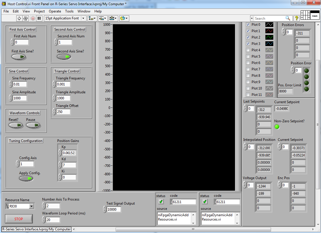
The host provides some very basic functionality for tuning, sending 2-axis trajectories, and comparing your success/debugging problems.
The top left pane provides an interface to any two of the four axis that the FPGA is capable of controlling. You can send a test Sine signal, test Triangle wave, or modify the code to send arbitrary points. You can reset or pause the waveform (although you should be careful not to exceed your maximum position error when resetting).
The tuning configuration is provided so axis can be tuned independently. It is recommended you perform your tuning on slow moving signals before increasing the signal frequency.
The general configuration is provided at the bottom of the VI. The R Series resource, number of axis the FPGA should process, host to target send rate, and analog voltage test signal (for debugging or triggering) are configurable. The Waveform Loop Period controls the rate the host sends points to the target. It is highly recommended that this interval is decreased for higher frequency signals.
Errors on both the primary loops in the code are displays (although warnings are typical, errors will stop the VI).
The right side shows raw debug information from controls on the FPGA. Every stage of the data pipeline is represented, from the requested setpoints, to the interpolated position, to the actual setpoints, voltages, encoder positions, and position errors.
Finally, the graph in the middle shows the signals being sent in comparison to the encoder feedback pulled from the lossy FPGA indicators. In order to make this lossless, a FIFO is provided (although not implemented on the host) which will sent encoder points at an interval the user may configure.

The host code is separated into a few simple sections. The following process is executed:
- Initialize the FPGA and configure the FIFOs.
- Configure the global properties of the motion system (position error, active states, etc).
- Configure each axis in use (in this case two axis are configured).
- If no errors have occured, begin the producer and consumer loops.
- The producer loop:
- Generates the points based on input parameters for the various function generators.
- Bitpacks those points with their axis number.
- Sends the points via the setpoint FIFO to the consumer loop.
- The consumer loop:
- Reads from the producer loop.
- If the read is successful, sends the value over the FPGA FIFO.
- Updates controls on the FPGA.
- Reads values from indicators on the FPGA.
- Upon stop or error, closes all queues and FIFOs.
- Closes the FPGA.
- Resets the stop buttom.
_____________________________________________________________
The FPGA VI
The FPGA VI provides a few tabbed screens which are shown in interactive mode. It is not recommended that this be run in interactive mode (and it was not tested). These tabs are meant to help the user organize their efforts in controlling the FPGA options.
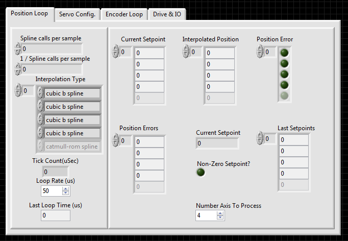
The position tab has some of the primary control options and debug information. The Number of Axis to Process allows the user to limit the work the FPGA must do to control multiple axis. If the user only wants to axis, they can prevent the FPGA from needlessly processing the other two axis splines and PID functions (which are very resource intensive).
It is recommended that the loop rate be 50us and the spline calls per sample be around 100. These should be set from the host.
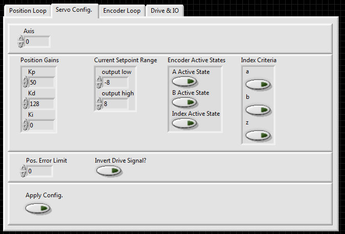
The configuration screen is provided for setting range and PID Gain information. It is highly recommended the these values be carefully configured before activating the FPGA.
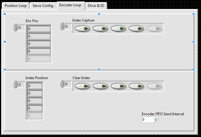
The encoder values may be read via the Enc Pos indicator for lossy communication. However, a FIFO is provided (and updated every Encoder FIFO Send Interval iterations) for lossless testing. This is increasingly useful the faster your loop rate is.
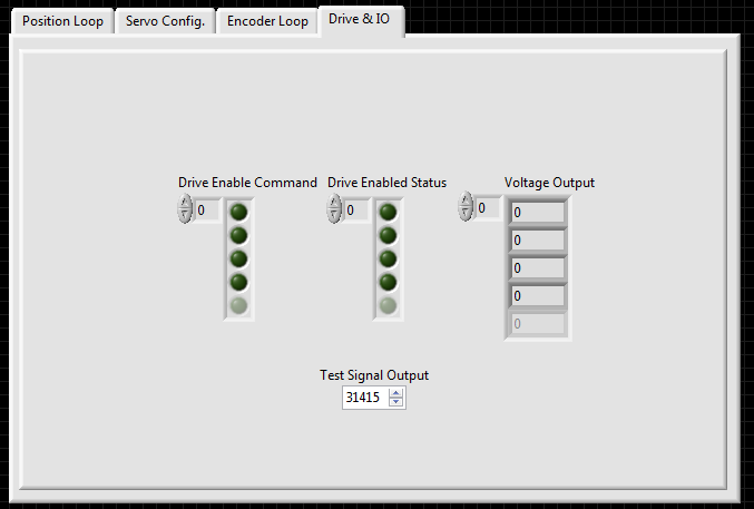
The drive IO section provides very basic enable and status information, voltage outputs, and a test analog output channel which are updated in the position loop.

The code is separated into a few discrete loops. The top loop provides a layer of abstraction for the host data pipeline. If the user wished the data points to be generated on the FPGA, they need only reprogram this loop to send the points from the top FIFO Loop to the Position/Spline Loop below.
The Position Loop or Spline Loop is where the core functionality occurs. This loop operates on values passed from the upper loop (note that it can only process one point at a time, meaning one axis at a time). It will perform a spline and PID, update all appropriate indicators, and pass setpoints to the voltage control loop below.
The loops below the position loop should never need to be modified. They are responsible for updating the encoder position, configuration, and various other variables.
_____________________________________________________________
Conclusions and Limitations
This example is meant as a starting point. Although there are advantages to performing Windows to FPGA motion control, it is important to realize that a constant stream of points is expected. Synchronization becomes a challenge and the user may find it useful to remove the host-generated points en lui of FPGA generated points (in the FIFO loop).
There are many display related challenges to displaying the lossless encoder locations along with their corresponding setpoints. For this reason, it is recommended that users record these values and compare them after the fact (instead of in real time).
With a properly tuned motion system, this example can allow a great degree of control for the user without the need of maintaining Real-Time code.
Although the number of Axis are limited to four in the example, with a sufficiently powerful FPGA, this value could be increased without architectural modification.
I hope this helps those interested in this sort of system!
Description-Separate-2Example code from the Example Code Exchange in the NI Community is licensed with the MIT license.
