This project is for an FPGA and allows a host to put table value/time pairs on the FPGA, and then have the FPGA maintain a linear interpolation between the points, with high precision timing of the analog outputs, digital outputs, and outputing this with a wave that can be up to 10 hours long without repeating.
If the intention is to create a repeating wave like a sine, or sawtooth, this is not the project for you. This was designed for electrical testing, where an output needs to follow a table of values. These values on the table can be paused, stopped, manually manipulated, and looped.
The code is currently saved in 2011, and compilied for a PCI-7831R card. I have changed the target to a 7841R and it also comiled without any issues so I susupect any FPGA that supports analog outputs should have no problem compiling.
Limitations
- The table of times and values only has 1024 points.
- The times for the analog and digital values are shared. Meaning there is only one table for time and that must correspond to the analog and the digital values
- AO0, DO0, and DO1 are the outputs that can be controled using the timing table.
- The analog input is relativly slow at 100KHz and cannot be much faster without increasing the FIFO buffer size.
- The time table resolution is down to the microsecond
- The analog output table resolution is down to the millivolt, but the actual output has more resolution then that
- The table of times cannot exceed 10 hours (36 Billion microseconds)
Speed
- The analog output loop rate runs around 336KHz.
- The digital output loop rate runs around 2.8MHz.
- The U64 Timer for the analog/digital output loops runs around 2.8MHz
- The analog input loop rate runs at 1KHz.
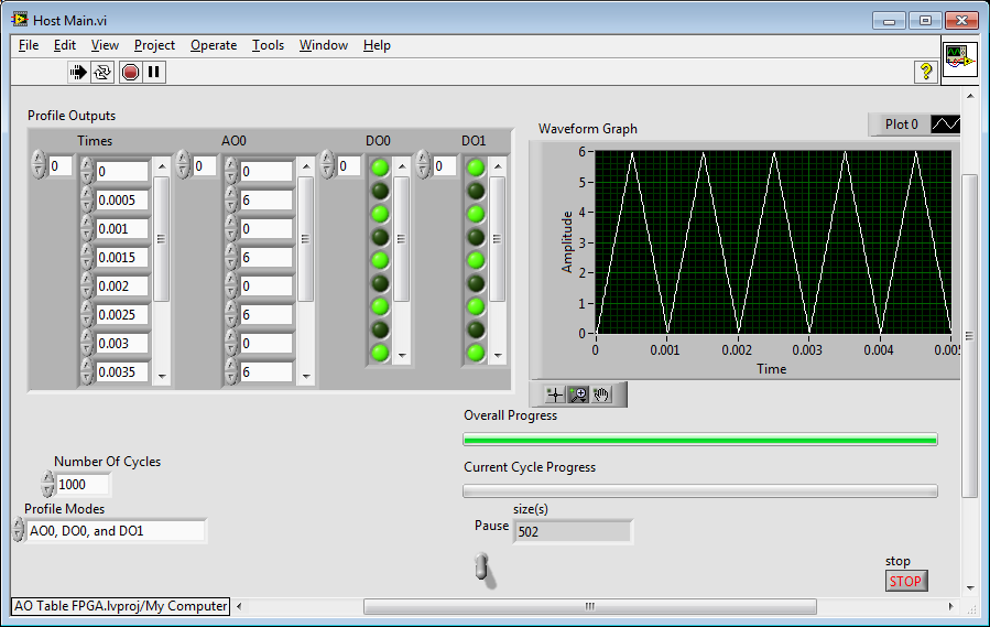
In the image above I tied my AO0 to my AI0 so I could sample my output I was generating. Notice how the FPGA determined what the output value should be between the points.


