Overview
This example synchronizes a cDAQ analog measurement with a E-Series analog measurement.
Description
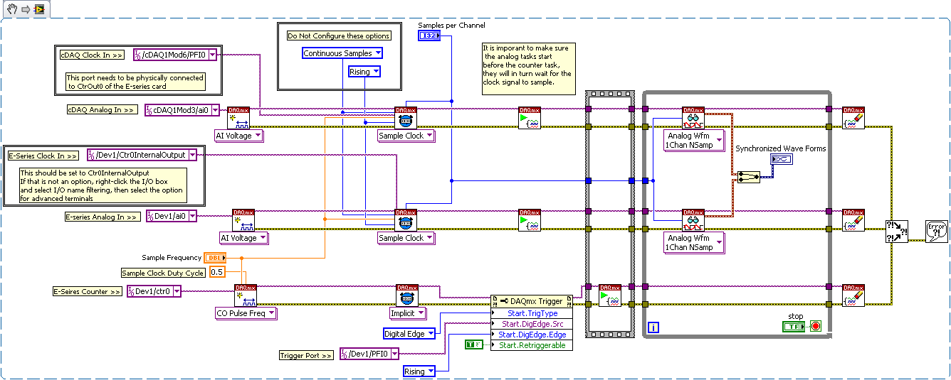
This example accomplishes this by using a counter task sourced from the E-series card as the sample clock for both the E-Series card and the cDAQ. The overall idea of this configuration is to configure an analog task for both the cDAQ and E-Series module. The trick is to use the internal counter output on the E-Series to source the sample clock for the E-Series acquisition and to physically connect the external counter output to a PFI line on the cDAQ. By starting the analog tasks first they will wait for the first tick of the sample clock that will commence the sampling simultaneously on the cDAQ and the E-Series card.
Requirements
Software
- LabVIEW 8.2 or compatible
- DAQmx 8.3 or compatible
Hardware
- Most NI C Series Digital Input Modules
- Most NI C Series Analog Input Modules
- NI E Series (60xxE) DAQ card. May work with other NI DAQ cards
Steps to Implement or Execute Code
- Configure the E-Series DAQ Ctr0 as the sampling clock. Be sure to use your Ctr0 configuration for all of your sampling properties such as, sampling frequency, samples per channel, and sampling mode.
- Configure the E-Series AI Voltage task. Use the DAQmx Timing VI to set the sample clock to the Ctr0InternalOutput. (This is accessed by right clicking the selection box and entering the I/O Filtering option then selecting the Show Advanced Terminal option.)
- Make sure your Analog and Digital Modules are in slots 5 and 6 of your cDAQ as those are the only ports that can access the PFI lines.
- Configure the cDAQ AI Voltage task. Use the DAQmx Timing VI to set the sample clock to the PFI0 input. (This will correlate with one of the digtal lines on the digital module.)
- Be sure to start the analog tasks first. They will start but there will not be a clock present, therefore they will not be sampling.
Additional Information or References
**This document has been updated to meet the current required format for the NI Code Exchange.**
