DAQmx Multifunction Synchronization with Shared Sample Clock
- Subscribe to RSS Feed
- Mark as New
- Mark as Read
- Bookmark
- Subscribe
- Printer Friendly Page
- Report to a Moderator
Products and Environment
This section reflects the products and operating system used to create the example.To download NI software, including the products shown below, visit ni.com/downloads.
- LabVIEW
Software
- NI-DAQmx
Driver
Code and Documents
Attachment
Description
Description-Separate-1Part of the M Series Synchronization with LabVIEW and NI-DAQmx Example Set
The second form of single device, multifunction synchronization involves sharing a sample clock. Sharing the sample clock is probably the most common way to synchronize single device operations because it ensures that the operations start at the same time and proceed at the same rate. The simultaneous analog voltage measurement and voltage generation example above could have also been achieved by sharing the AI or AO Sample clock between both subsystems. A great example of when to use this method is when you want to correlate digital and analog waveform operations on an M Series device.
Unlike E Series devices, the M Series device can be used for hardware-timed digital operations. However, the digital subsystem of an M Series device does not have the ability to divide down one of the timebases to create an internal clock for digital input or output operations. An external signal or one of the many internal signals from another subsystem must be provided as the digital sample clock. For example, one can synchronize digital and analog operations by sharing the AI or AO Sample Clock as the source of your DI or DO Sample clock. To sample a digital signal independent of an AI, or AO operation, a counter or an external signal can be configured to generate the desired DI Sample Clock.
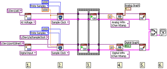
The example below demonstrates how to synchronize an analog input operation with a digital input operation. The digital acquisition will not begin until the analog input operation has started and the AI Sample Clock is generated.
Figure 1 Shared Sample Clock and Simultaneous Start
In the example shown above, the digital input circuitry uses a shared sample clock to synchronize analog and digital input.
- In step 1, the analog input and digital input channels are created. The initialization procedure acquires the basic information needed to describe the operation.
- Using two DAQmx Timing VIs, the sample modes are defined as continuous or finite acquisitions. The sample mode is determined by the specific application. Because the sample clock is being shared, the two operations should use the same sample rate. In this example, the rate is 1 kHz. Additionally, the DAQmx Timing VI should set the digital timing source to be the analog input sample clock. This causes the digital input circuitry to latch the digital lines at the same time that the analog channels are sampled.
- At this point, the analog input and digital input operations are started with the DAQmx Start Task VI. The sequence structure ensures that the digital input process has been started and is waiting for the analog input to start. As stated before, the digital task does not have a defined trigger; however the digital task will not start until the analog input sample clock is available. The analog input sample clock will be available when the analog input task is started.
- The DAQmx Read VIs will each read a finite number of samples.
- Finally, the tasks are cleared.
- The error clusters are merged and passed to a simple error handler.
Description-Separate-2
Example code from the Example Code Exchange in the NI Community is licensed with the MIT license.

