Introduction
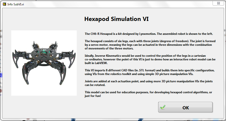
The CH6-R Hexapod is a kit designed by Lynxmotion (shown below).
A hexapod consists of six legs, and rather than using wheels to move around, it uses it's legs to walk, much like a beetle or any other six-legged insect you can think of.
Typically, controlling such a beast as a hexapod can be a tough challenge, each leg must be co-ordinated well so that a desired 3D movement can be achieved. Usually a leg would consist of 2 or more servo motors, so co-ordinating this into high level walking movement isn't easy! Well, although this VI won't show you how to do that (don't worry, I'm working on that for my next example) it will show you how you can import build such a robot in LabVIEW. In this VI, the hexapod I've put together is interactive, so all the joints can be controlled! Scary stuff!
This is really useful if you're planning to build the algorithms for controlling the movement, and you won't need to have a real hexapod to do it! Also, the techniques applied could easily be applied to building other robot simulations. Heck, there's no reason why you couldn't build a simulation of anything in LabVIEW!
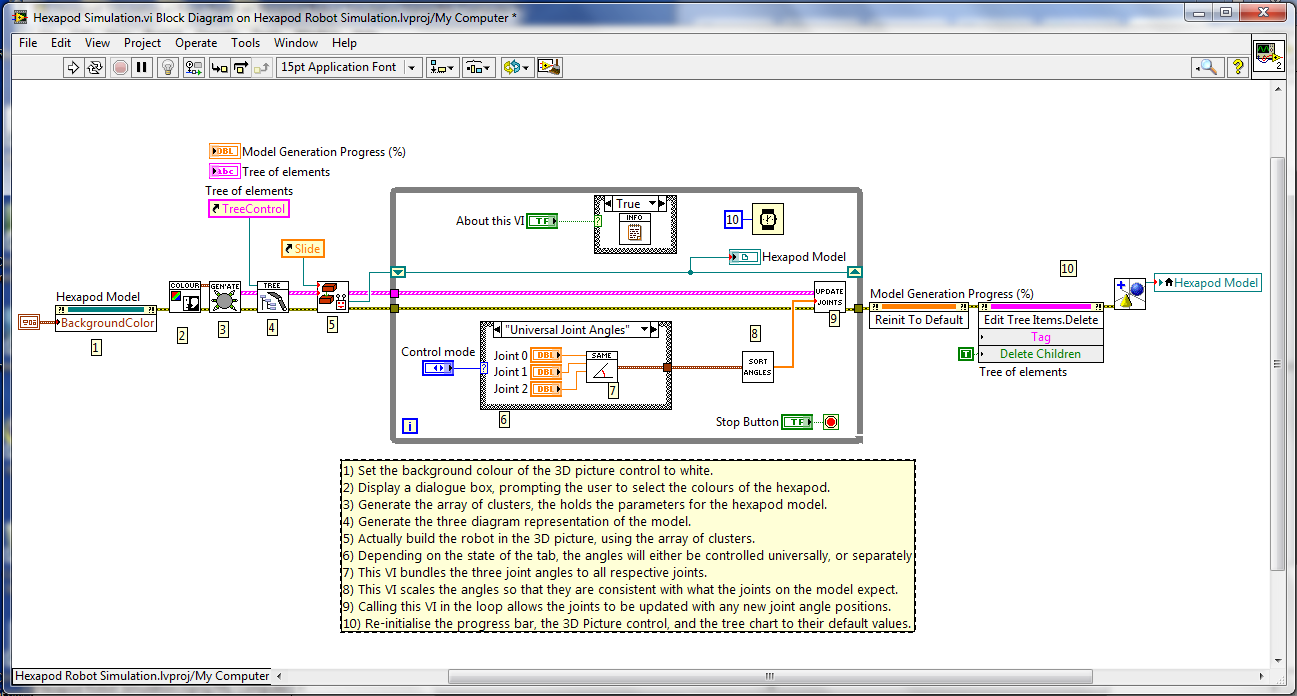
How it works
The point of this VI is just to demo how an interactive robot model can be
built in LabVIEW.
This VI imports 8 different CAD files (in .STL format) and builds them into specific configuration, using VIs from the robotics toolkit and using simple 3D picture manipulation VIs. The position of the joints was figured out by trial and error, and I've made sure that everything is in the correct position.
Joints are added at each actuation point, and using more 3D picture manipulation VIs the joints can be rotated. For each leg there are three joints, which I've imaginatively named joint 0, joint 1, and joint 2. In this VI you can either control all the joint groups together, or alternative have control of each individual joint.

You'll notice it can take a while (up to 20 seconds or so) to generate the 3D model. This is normal, it turns out there's quite a bit to import, so the program does take its time. However, once the model is generated, moving the joints is almost instant.
I hope you enjoy this VI, as I said, I'm working on an addition to this VI, in which the inverse kinematics is used in the simulation, allowing for more 'real' movements.
I've included all the STL files for the CAD model in the attached file, make sure you keep the folder structure the same, my VIs will look in a specific folder within the project folder, to find these files.
Bye for now!
