- Document History
- Subscribe to RSS Feed
- Mark as New
- Mark as Read
- Bookmark
- Subscribe
- Printer Friendly Page
- Report to a Moderator
- Subscribe to RSS Feed
- Mark as New
- Mark as Read
- Bookmark
- Subscribe
- Printer Friendly Page
- Report to a Moderator
The Medical Image 2D Viewer control is used to display the transverse plane (X-Y), coronal place (X-Z), and sagittal plane (Y-Z) that intersect the coordinates of 3D volume data. The 2013 version has the following new features:
- Supports zooming, moving and dragging
- Zoom in/out: mouse wheel
- Change image index (move cursor): Alt + mouse drag
- Drag image: mouse drag
- Supports color image rendering (RGB, palette color)
- Automatically detects the image orientation from DICOM tags
This document teaches you how to write a simple image viewer which animates your 2D slices by using the Medical Image 2D Viewer control. There are 4 main steps to writing an Animate 2D Slices, VI as the following block diagram shows:

1. Customize the Medical Image 2D Viewer Control
You can set some properties using the property nodes to customize the Medical Image 2D Viewer.

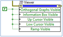
Set the Orthogonal Graphs Visible, Information Box Visible, and Ramp Visible property nodes to False and run the VI. Only the main graph will be visible on the Medical Image 2D Viewer.
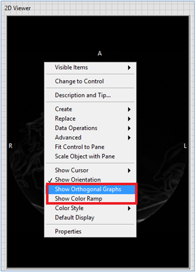
You can also use the shortcut menus to make the Orthogonal Graphs or Color Ramp visible/invisible.

2. Load Image Data Using the Read Image Express VI
Refer to the Read Image Express VI documents for details. (3D Image)
3. Set the Image Data and Attributes for the Medical Image 2D Viewer
The 2013 version of the Biomedical Toolkit contains a new helper VI called Medical Image 2D Viewer Helper.vi that appears when dropping the Medical Image 2D Viewer Express VI on the block diagram. The Medical Image 2D Viewer Helper is a polymorphic VI with 16 instances. This help VI has the following functions:
- Detect the image orientation from the DICOM tags in input and rotate the input image data according to the image orientation property.
- Get common image attributes, such as color space, color map, and window, from the image attributes in and DICOM tags in inputs. The helper VI then sends these attributes to the Medical Image 2D Viewer through the property nodes.
You can connect the Read Image Express VI and the Medical Image 2D Viewer Express VI as shown in the following snapshot.

4. Set the Slice Index for the Medical Image 2D Viewer
Set the slice index sequence to the Z Coordinate property node within a while loop. The Medical Image 2D Viewer displays the slices in a loop mode. When the slice index reaches the maximum value, it returns to 0.

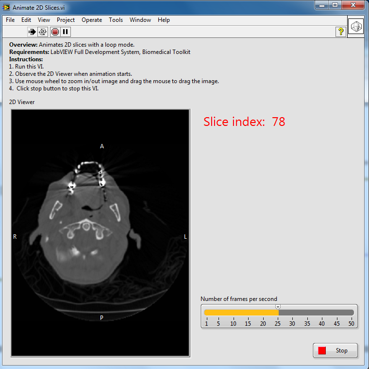
The following is the front panel of the example VI described in this document.

