LCD Device Driver for FPGA Applications
- Subscribe to RSS Feed
- Mark as New
- Mark as Read
- Bookmark
- Subscribe
- Printer Friendly Page
- Report to a Moderator
Products and Environment
This section reflects the products and operating system used to create the example.To download NI software, including the products shown below, visit ni.com/downloads.
- LabVIEW Real-Time Module
- LabVIEW
Software
- NI RIO
Driver
Code and Documents
Attachment
Synopsis
This collection of subVIs provides support for the LCD on the Spartan-3E Starter Kit FPGA development board. The high-level subVIs Show Hex on LCD.vi and Show Character on LCD.vi display user-defined numerical values in hexadecimal format and as ASCII characters; lower-level subVIs provide access to the LCD controller command set, and serve as the foundation for other yet-to-be-created “Show” subVIs. Multiple instances of the “Show” subVIs may be used in a single application VI, with each appearing to independently control its own region of the LCD.
Description
The Spartan-3E Starter Kit FPGA development board includes a 16-by-2 character LCD (liquid crystal display). The subVIs Show Hex on LCD.vi and Show Character on LCD.vi format user-supplied values into a sequence of LCD controller commands, and push them to Manage LCD.vi via a FIFO. Manage LCD.vi in turn translates the commands into suitable timing waveforms to operate the LCD controller hardware interface.
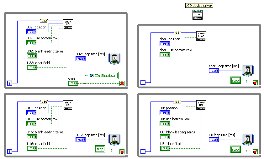
The application VI LCD Driver Demo.vi displays four independent while-loop index values in hexadecimal format as well as in ASCII. All controls for the Show Hex on LCD.vi and Show Character on LCD.vi appear on the front panel; three instances of the polymorphic Show Hex on LCD.vi illustrate how it can accept U8, U16, and U32 datatypes and automatically set the correct field width. Vary the loop time sliders to adjust the rate at which each field updates. Note that each value appears to control its own region of the LCD screen.

Steps to Complete: Running the Demonstration
1. Download LCD Driver.zip and extract to a suitable folder
2. Open LCD Driver.lvproj
3. Open the Top-Level VIs virtual folder, and then open and run [top_level] LCD Driver Demo.vi
4. Operate the front panel controls to change the field positions, blank leading zeros, etc. Vary the loop time sliders to adjust the rate at which each field updates.
Steps to Complete: Using the LCD driver in your own application
1. Open your existing LabVIEW project that includes an FPGA target (the target must have an LCD such as that used on the Spartan-3E Starter Kit)
2. Right-click on FPGA Target and choose Add Folder (Auto-Populating)
3. Select the folder LCD Device Manager from the .zip distribution
4. Add the required FPGA I/O resources for LCD support: Right-click on FPGA Target, select New and then FPGA I/O, select LCD, click the right-pointing arrow, and then click OK; repeat for the following StrataFlash I/O: SF_CE0, SF_D8, SF_D9, SF_D10, and SF_D11
5. Create the “LCD Command” FIFO: Right-click on FPGA Target, select New and then FIFO; enter the following information into the dialog box: Name = LCD Command, Type = Target-Scoped, Data Type = U16, Number of Elements = 1, and Implementation = Flip-Flops
6. Create the “LCD Semaphore” FIFO: Right-click on FPGA Target, select New and then FIFO; enter the following information into the dialog box: Name = LCD Semaphore, Type = Target-Scoped, Data Type = Boolean, Number of Elements = 1, and Implementation = Flip-Flops
7. Open your application VI
8. Select the block diagram, right-click on an open area, choose Select a VI, and then select Manage VGA (Spartan-3E Starter Board).vi. Place this subVI in its own area on the block diagram; do not place it inside a loop, since the subVI already contains it own loop.
9. Select the block diagram, right-click on an open area, choose Select a VI, and then select LCD Interface.vi. Connect this global variable to the “stop” button signal that you use to shutdown the entire VI.
10. To display a U8, U16, or U32 integer datatype as a hexadecimal value, choose Select a VI and then select Show Hex on LCD.vi.
11. To display a U8 integer as an ASCII character, choose
Select a VI
and then
Show Character on LCD.vi.Additional Notes
1. The StrataFlash memory shares some connections with the LCD, and is disabled by Manage LCD.vi
2. In principle, the “Show” subVIs can connect anywhere that a standard LabVIEW indicator would be used, but keep in mind two practical considerations: (1) transferring commands to the LCD takes time, and (2) each instance of a “Show” subVI consumes its own chunk of FPGA fabric.
To elaborate, most LCD commands require 48 microseconds and up to 1,648 microseconds for the “Clear Display” and “Return Cursor Home” commands. A single call to Show Hex on LCD.vi with U16 datatype generates five LCD commands: a starting address followed by four ASCII characters, requiring a total of 240 microseconds. This time assumes that no other “Show” subVIs send messages to the FIFO. Each “Show” subVI locks the FIFO input to ensure that its commands arrive in the correct sequence. Consequently, care must be exercised to ensure that the “Show” subVIs operate in loops that balance the needs of a responsive display and competing users of the display.
Since each instance of a “Show” subVI requires its own chunk of space on the FPGA, whenever possible use a case structure or similar construct to select one source of information out of multiple sources that ultimately connects to a single “Show” subVI, rather than placing a “Show” subVI for each data source.
3. Study the high-level "Show" VIs to gain an idea of how to use the low-level subVIs to create your own high-level VIs, for example, to show an unsigned integer in decimal format or to send an array of U8 values as an ASCII string.
Known Issues
1. The “blank leading zeros” control only works on for the U32 version of Show Hex on Display.vi
2. Manage LCD.vi does not properly respond to its “shutdown” signal. Use the abort button to stop execution of LCD Driver Demo.vi.
3. In my experience, top-level applications constructed with these LCD device driver subVIs only compile properly with LabVIEW 2009. The version 8.6 project is provided "as is", and may work satisfactorily for only a single "Show" subVI.
References
1. See Chapter 5 of the Spartan-3E Starter Kit Reference Manual for a detailed discussion of the LCD controller, interface bus timing, and command set. If the reference manual link has changed, refer to the “Support” section of the Digilent website (www.digilentinc.com).
2. The Spartan-3E Starter Kit board features the PowerTip PC1602-D Character LCD module (http://www.powertipusa.com/pdf/pc1602d.pdf), a 16x2 character liquid crystal display (LCD) operated by the Sitronix ST7066U Character LCD Controller (http://www.sitronix.com.tw/sitronix/product.nsf/Doc/ST7066U?OpenDocument).
3. asciitable.com provides a convenient way to determine the numerical value of a desired ASCII character for use with Show Character on LCD.vi
Example code from the Example Code Exchange in the NI Community is licensed with the MIT license.
