- Document History
- Subscribe to RSS Feed
- Mark as New
- Mark as Read
- Bookmark
- Subscribe
- Printer Friendly Page
- Report to a Moderator
- Subscribe to RSS Feed
- Mark as New
- Mark as Read
- Bookmark
- Subscribe
- Printer Friendly Page
- Report to a Moderator
myDAQ mini-lab: Op Amp IV – Inverting and noninverting amplifiers
Course Linkage: Linear Circuit Analysis >> Operational Amplifiers >> Inverting Amplifier, Noninverting Amplifier
Measurement Techniques: ELVISmx DMM (voltmeter, ohmmeter), function generator, oscilloscope
<hr width=”75%”>
Introduction
Overview: Electronic systems frequently need to amplify low-level signals. For example, a sensor may produce a voltage signal in the millivolt range but subsequent signal-processing circuitry requires the signal to be in the volt range. An operational amplifier combined with a pair of resistors provides necessary amplification for a wide variety of electronic systems.
Objectives: In this mini-lab you will:
- Construct two types of op-amp-based amplifiers: inverting and noninverting
- Observe the gain characteristics of the two amplifiers
- Learn the design equations necessary to select a desired amplifier gain
- Understand the signal source loading effects of each type of amplifier
Equipment
- NI myDAQ
- Breadboard
- Connecting wire
- Alligator clip test leads
- Texas Instruments (TI) TL072 dual op amp (two) or similar device for a total of three op amps
- Resistors, ¼-W 5% carbon film: 1.0K (two)
- 10K potentiometer (two)
Deliverables
- Submit your work in the form of a homework set problem or lab notebook entry according to the requirements of your instructor
- Submit your work for each underlined boldface item, and clearly label the item with its section letter and task number
A. Experience amplifier behavior by measurement
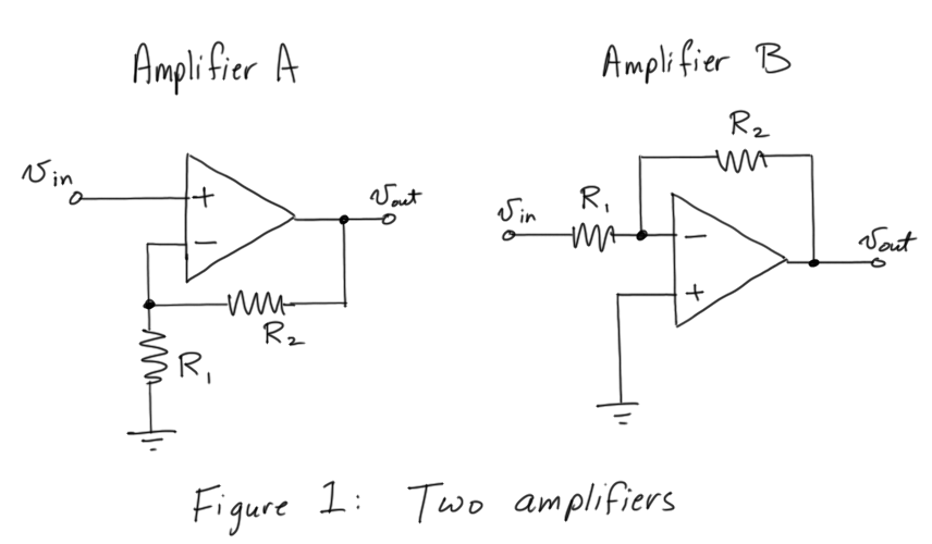
- Draw the two amplifier circuits shown in Figure 1:
- Before you construct the circuit, set up the ELVISmx DMM as an ohmmeter, and measure and record the resistance of each resistor and each potentiometer (measure the resistance between the outer terminals).
- Set each potentiometer dial to its midpoint position.
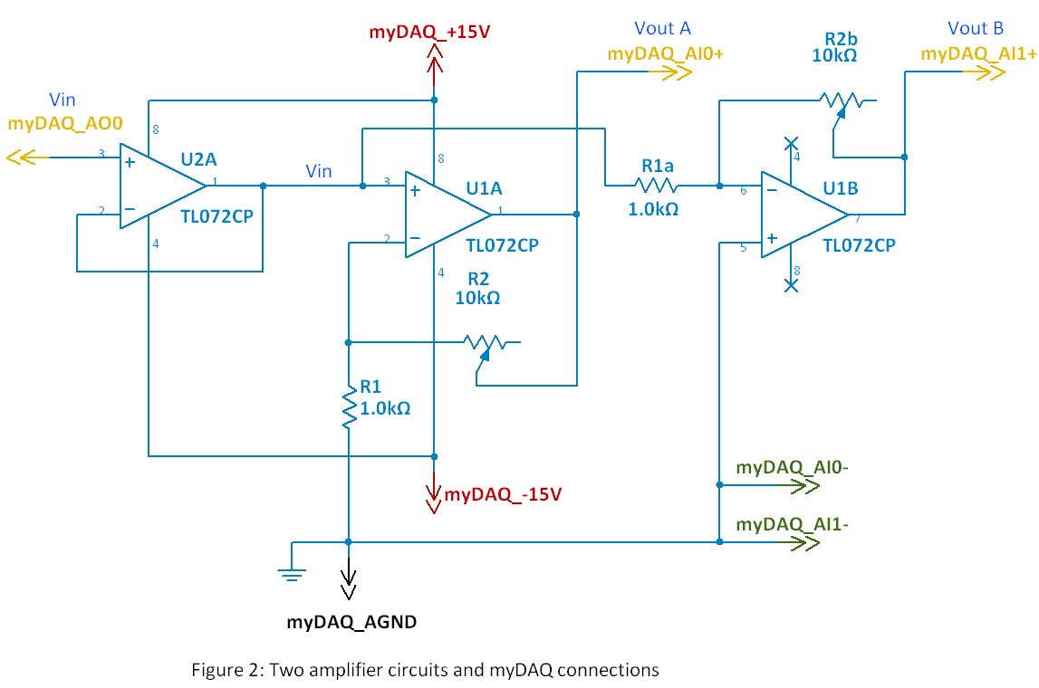
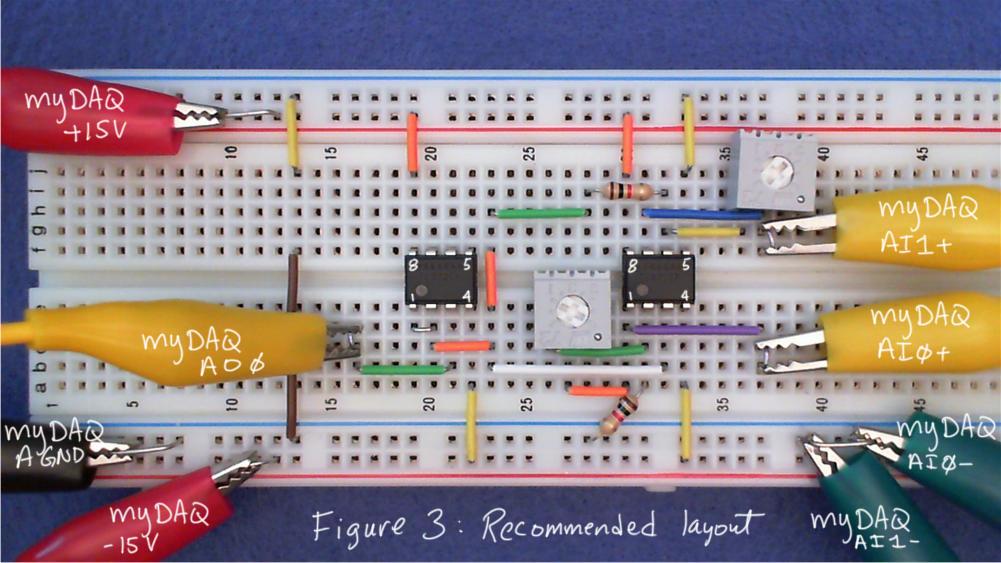
- Construct the circuit of Figure 2 with myDAQ and a breadboard. The third op amp (U2 on the left side) is wired as a voltage follower to increase the current drive ability of the signal input generated by the myDAQ analog output. The voltage follower replicates the signal Vin and presents it to both amplifier inputs. See Figure 3 for the recommended layout and Figure 4 for the myDAQ connections (click image for full detail):

- Download and run “Set AO Voltage and Show AI Voltage.vi” linked at the bottom of this document. Slider control AO0 sets the voltage Vin applied to both amplifiers. The output of Amplifier A appears on the slider indicator AI0 and the output of Amplifier B appears on the indicator AI1.
- Observe the output of each amplifier as you vary the input voltage. Respond: Which amplifier inverts the sense of the input, i.e., increasing the input voltage causes the output to become increasingly negative?
- Set the input voltage to exactly 1.00 volts (type “1” directly into the text box and press “Enter”). Adjust the potentiometer for Amplifier A until the output reads 2.0 volts. The amplifier now has a gain of 2 (1 volt on the input produces 2 volts on the output). Vary the input and confirm that the output is always twice that of the input.
- Repeat the previous step, this time adjusting Amplifier B to make its output five times as large as its input.
- Experiment with the gains of both amplifiers. Respond: Which amplifier can be adjusted to have a gain less than unity, i.e., the output signal is an attenuated version of the input?
- Respond: Which amplifier (A or B) should be called an “inverting” amplifier and which should be called a “noninverting” amplifier?
The following video shows some expected results for this section:
B. Learn the underlying principles
The following video tutorial introduces the inverting and noninverting amplifiers and presents the equations that may be used to select specific values for amplifier gain. The input resistance of each amplifier is also discussed:
C. Connect the principles to your measurements:
- Adjust the inverting amplifier to have a gain of -3 and the noninverting amplifier to have a gain of 5.
- Calculate the expected potentiometer values for the gain values of the previous step.
- Remove the potentiometers from the circuit (or ensure that at least one terminal is disconnected), and measure and record the potentiometer resistance. Be sure to measure between the same two terminals that form the variable resistance.
- Compare your calculated and measured results by reporting percentage difference.
- Reconnect the potentiometers in your circuit.
- Set up the ELVISmx DMM as an ammeter. Remove the wire connecting the output of the voltage follower to the input of the noninverting amplifer and replace it with the DMM probes. Use probe clips if you them available, or coil a wire around the probe tip with one end of the wire long enough to connect into the breadboard.
TIP: Wrap the wire around the probe tip to form a coil, remove the coil and bend it slightly, and place it back on the coil (bending the coil ensures a snug fit):
- Vary the input voltage while observing the DMM ammeter. Record the maximum current you observe entering the noninverting amplifer input.
- Reconnect the voltage follower to the noninverting amplifier, and then remove the wire that connects the voltage follower output to the inverting amplifier. Re-establish the connection with the ammeter.
- Vary the input voltage while observing the ammeter. Record the maximum current you observe entering the inverting amplifier input.
- Stop the “Set AO Voltage and Show AI Voltage.vi” application.
- Start the ELVISmx Function Generator and the ELVISmx Oscilloscope. The function generator produces its output on AO0 (already connected to your circuit’s Vin). Connect AI0+ to the input voltage Vin and connect AI1+ to the output of the noninverting amplifier.
- View the input and output signals simultaneously on the oscilloscope. The default values for the function generator are acceptable. Use edge-type triggering on the oscilloscope to stabilize the display.
- Try the three different signal shapes (sine, triangle, and square), and try varying the gain of the amplifier.
- Connect AI1+ to the output of the inverting amplifier, and then repeat Steps 7 and 8.
- Create a representative screenshot of the oscilloscope display for each of your two amplifier circuits.
Build your intuition:
Reflect on the following points:
- Ideally a voltage amplifier does not draw any current from its signal source. Respond: Based on your measurements, which of the two amplifiers approaches this ideal behavior? Which amplifier appears to fall far short of this ideal?
- A gain magnitude less than one is occasionally useful. Respond: For which amplifier type is this an impossibility?
- When amplifying audio signals, the ability to completely mute the signal (gain = 0) may be necessary. Respond: Which is the only amplifier type that can completely mute a signal?
For more information
