- Document History
- Subscribe to RSS Feed
- Mark as New
- Mark as Read
- Bookmark
- Subscribe
- Printer Friendly Page
- Report to a Moderator
- Subscribe to RSS Feed
- Mark as New
- Mark as Read
- Bookmark
- Subscribe
- Printer Friendly Page
- Report to a Moderator
NI Engine Simulation Toolkit for NI VeriStand
Overview
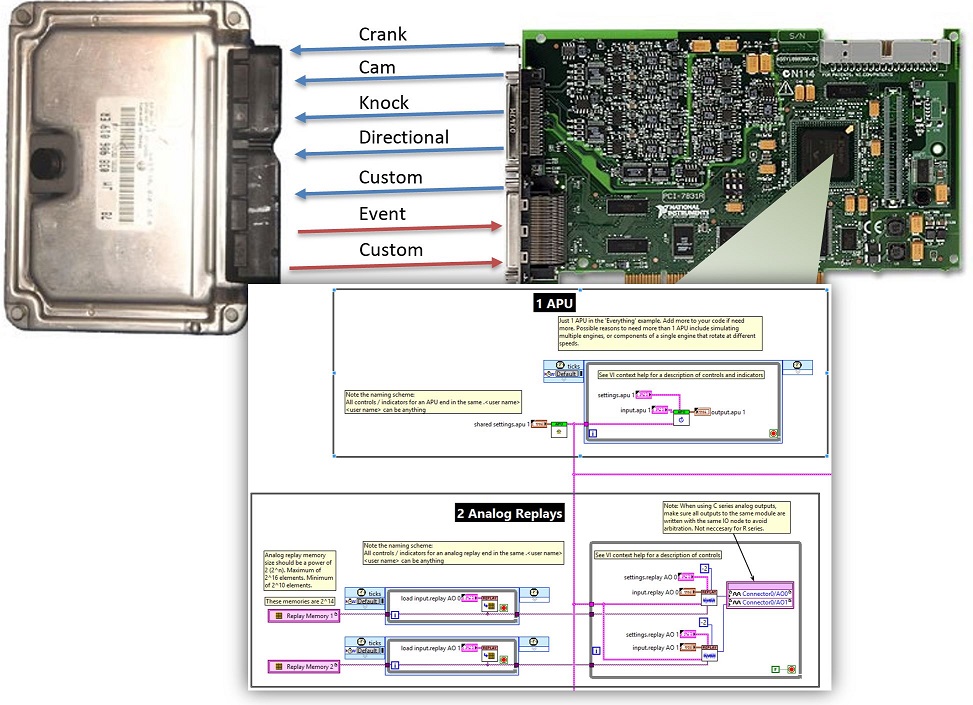
The Engine Simulation Toolkit for NI VeriStand provides a powerful, open-source, configuration-based experience for validating engine control units (ECUs). In NI VeriStand, simply load a LabVIEW FPGA bitfile that includes Engine Simulation Toolkit IP and configure the measurement and generation options. Combine with your own engine physics model to create a complete ECU hardware-in-the-loop system.
The FPGA IP library includes examples so novices and experts can transform their NI FPGA hardware into sophisticated ECU testing tools.


Components
A LabVIEW FPGA bitfile can be quickly built with any number of the following components, provided by the Engine Simulation Toolkit's FPGA library. The NI VeriStand custom device loads a selected FPGA bitfile, discovers Engine Simulation Toolkit components contained within, and makes them available for configuration and execution.
Angle Processing Unit
|
ECU Event Timing Capture
|
Digital Pattern Generation
|
Analog Replay
|
Knock Sensor Simulation
|
Directional Speed Sensor Simulation
|
Detailed Specifications
|
Angle Processing Unit |
|
|
Digital Pattern Generation |
|
|
Analog Replay |
|
|
ECU Event Timing Capture |
|
|
Directional Speed Sensor Simulation |
|
|
Knock Sensor Simulation |
|
Open Source
This add-on is provided open source. If you are interested in contributing your code additions back to the toolkit, please post in our feedback forum linked at the bottom.
- To modify or extend the FPGA IP libraries, LabVIEW FPGA 2013 or later is required
- To modify or extend the Custom Device, LabVIEW 2013, LabVIEW RT 2013, and the LabVIEW FPGA Advanced Session Resources are required
- The source code for this custom device can be found on GitHub.
Feature Roadmap
The following features are being investigated for future inclusion in the toolkit. There is no schedule on these items, and they are not guaranteed to be included. They are listed in no particular order.
- O2 Sensor Simulation
- Multiple APU synchronization within one FPGA or spanning multiple FPGAs
- ECU event waveform capture
- Ability to switch between multiple, pre-configured, analog replay's at run time when a crank or cycle finishes. For the purposes of playing a different replay (perhaps one with a malformed tooth) for one cycle
- In cycle speed variation for the APU based on number of cylinders, cylinder offsets, and % variation
- Ability to switch to a different variation profile for a single cycle to simulate the speed profile of a misfire
- A fault function inside the APU to go to zero speed when reaching a certain position
- A graph of all generated signals on the APU page
- Import / export of all event timing settings
- Injector simulation to calculate a fuel mass value that passed through during active time
- Digital filtering for event timing inputs. Helps with noisy digital lines often due to real loads (injectors, sparks)
Required Software
- To deploy: NI VeriStand 2013 or later & NI-RIO 13.1 or later. Caution: Using NI-RIO 13.0 will cause system instability!
- To create bitfiles: LabVIEW FPGA 2013 or later
Version History
Custom Device
1.3.2
- <Feature> Added bitfile refreshing. The user can now add or change features in their FPGA code, recompile the bitfile, then select Reload Bitfile from the top of the main page. The user could also right click on the main Addon section in the tree view and select Reload Bitfile. Any objects (i.e digital patterns, analog replays, etc.) that have the same bitfile name as before will remain in the project. Any previous objects that can't be found by bitfile name will be removed. Any new objects found will be available for adding in the normal ways. Note that changing the bitfile path still removes everything.
- <Feature> Added import and export of digital patterns. The user can now import and export digital patterns by going to the Digital Patterns page and right clicking on the desired pattern in the Patterns view and selecting Import or Export.
- <Feature> Added auto-increment feature for edge removal on digital patterns. The previous operation of removal was to select the desired edge in the Crank Angle plot and select the Add button by the Edges Removed view. Then, the user had to move the cursor to the next edge and repeat. Now, the user can continue to select the Add button and the next edge will automatically be removed. This makes removing multiple sequential edges simpler.
1.3.1
- <Bug> Fixed a critical issue that could cause bitfiles compiled with previous versions of the Engine Simulation Toolkit FPGA IP to no longer work with new versions of the Engine Simulation Toolkit Custom Device. Users would see error -63195. For example, using a bitfile compiled with IP version 1.2 with custom device version 1.3.
1.3.0
- <Feature> Added support for EST FPGA Library version 1.3.x. Bitfiles compiled with EST FPGA library 1.3.x and loaded by the custom device get those updates as well
- Note that Digital Pattern Generation faulting is not currently linked to directional speed sensor simulation. So faulting the digital pattern at run time will not yield a faulted directional speed sensor. This is noted in known issues and will be implemented in a future revision.
- <Bug> Fixed an issue related to storing the user's bitfile on the RT target. It was being stored on the target without the .lvbitx extension which could be confusing.
1.2.8
- <Bug> Fixed an issue that on some computers, the browse pattern (i.e. *.csv) in the analog replay file load dialog could appear would an extra *. at the beinging of it
1.2.7
- <Bug> Fixed an issue introduced in 1.1.0 where knock sensor simulation probability values between 1% and 99% (inclusive) behaved as if probability was set to 0%.
1.2.6
- <Bug> Fixed an issue introduced in 1.2.3 that caused error 1055 to occur when clicking on the Digital Patterns page if more than 1 pattern was present in the system definition file
1.2.5
- <Bug> Fixed an issue where analog replay, digital pattern generation, and directional speed sensor FPGA IP would not be initialized correctly if no IP of that type was imported to the system definition. For example, if four analog replays existed in your bitfile and you imported just 1 to the system definition, this would work fine. However, if you imported none of them, the unused IP would not be initialized correctly.
1.2.4
- <Bug> Fixed an issue that error -8719 would occur during deployment if all event measurements present in the bitfile were not added to the system definition
- <Bug> Fixed an issue that event capture data was not correct if all event captures present in the bitfile were not added to the system definition
1.2.3
- <Bug> Several fixes and improvements to digital pattern generation GUI
- Fixed that tooth add/remove editing controls were initialized incorrectly when loading the page with exactly 1 digital pattern configured
- Fixed that attempting to edit the base pattern by adding and removing teeth incorrectly added and removed the adjacent tooth instead of the one specified
- Fixed that editing an added or removed tooth incorrectly saved your edit as of the adjacent tooth instead (i.e. editing a tooth 59 removed edge would save that edit as a tooth 58 removed edge instead)
- Fixed that editing an added or removed tooth did not immediately update the listbox describing all teeth added or removed
- Fixed plot legend for digital patterns to always say: base, remove, add. Previously it could say things like: base, remove, remove
- Slight improvements to GUI formatting for added teeth editing
1.2.2
- <Bug> Fixed an issue when selecting data for a analog replay. The drop downs for group and channel were not refreshing the data display when their value was changed.
1.2.1
- <Bug> Fixed an issue with event measurement where a window with both negative minimum and maximum angles (like -400 to -100) did not work as expected.
- <Bug> Fixed an issue when designing digital patterns. In some cases, it was impossible to add teeth in the -360 to 0 degree span on a 720 degree pattern.
- <Change> On the digital patterns page, teeth are now displayed as 1 indexed instead of 0 indexed. This is a GUI change, so existing patterns are not modified.
1.2.0
- <Feature> Added support for EST FPGA Library version 1.2.x. Bitfiles compiled with EST FPGA library 1.2.x and loaded by the custom device get those updates as well
1.1.1
- <Bug> Fixed a critical issue preventing event measurement windows with a negative minimum angle (i.e. -10 degrees) from working in certain situations
1.1.0
- <Bug> Fixed that the custom device would print to the screen error -805 when undeploying. This error didn't mean anything so this is a cosmetic fix.
- <Feature> Added support for EST FPGA Library version 1.1.x. Bitfiles compiled with EST FPGA library 1.1.x and loaded by the custom device get those updates as well
1.0.0
- Released
FPGA Library
1.3.0
- Overall FPGA utilization and timing is approximately the same as 1.2
- Slightly reduced resource usage and improved timing of Directional Speed Sensor Simulation
- Slightly reduced resource usage and improved timing of APU
- Slightly increased resource usage and worsened timing of Digital Pattern Generation
- <Feature> Implemented support for run-time faulting of Digital Pattern Generation by removing a specified tooth or forcing a region high/low for the specified number of rotations (or indefinitely)
- <Change> Removed support for 2, 6 and 8 stroke engines as the APU logic was incorrect and these engines are not used by industry HIL testing
1.2.0
- <Feature> Event measurement VI is now polymorphic with "40MHz" and "Non-40MHz" instances. The 40MHz instance is new and saves considerable FPGA resources. Use this only when running your event measurement code in a 40MHz loop. The "Non-40MHz" instance is the same as previous versions of this toolkit and works in any speed loop, but uses more resources.
1.1.0
-
FPGA LUT utilization for event measurements is increased
-
FPGA timing characteristics are approximately the same
-
<Bug> Fixed an issue with an event measurement window spanning the entire cycle. Previously, with a full cycle window, event timing measurement would falsely report an "all active window" and failed to report "orphan starting" and "orphan ending" edges if an event spanned from the end the window to the beginning. For example: if the event measurement window was 0 to 720 degrees and an event started at 700 degrees of cycle 0 and finished at 20 degrees of cycle 1. This fix is internal to the Measure Events.vi.
-
<Bug> Fixed an issue where, when there were multiple parts of NI VeriStand accessing the same FPGA target, start angle and stuck active limit were not applied to the FPGA. Therefore the engine always started at zero degrees and stuck active limit was 0ms (causing false warnings). This fix requires you update your top level FPGA diagram. See the shipping examples. There is a new SCTL around the Create APU Register Bus.vi and a new boolean control inside that SCTL.
-
<Bug> Fixed an issue that prevented full range windows that wrapped the zero from working. For example, -360 to 360 or -10 to 710.
1.0.0
- Released
Known Issues
- When the custom device loads a bitfile with multiple APUs, there is no filtering of available components per APU inside the system explorer. This allows a user to add the same FPGA component (like a digital pattern generation) under multiple APUs or add a resource under an APU it is not physically wired to inside the FPGA. Each of these would be an invalid configuration.
Workaround: The provider of the bitfile should inform the user of the custom device which FPGA components are under each APU, and the user should restrict themselves from improper configuration. - Selecting a tooth source for the directional speed sensor allows you to select digital patterns with a length other than 360 degrees which are invalid and will result in an error when upon deploy.
- When using NI-RIO 13.1, 14.0, or 14.1, you may see warning 63186 from the custom device, this slightly degrades real time execution performance (about 10%).
Workaround: On Windows open or create %ALLUSERSPROFILE%\National Instruments\NI-RIO\nirio.ini and modify TableSegmentSize=16 to a higher value. On RT, the file is at, or must be created at c:/ni-rt/system/nirio.ini. The key must be under a section in the ini named [General]
To resolve: Use NI-RIO 15.0 or later when it is released. - NI VeriStand will load bitfiles containing engine simulation toolkit IP even if they do not exactly follow the required naming scheme for the engine simulation toolkit FPGA components. However, an error will be seen when attempting to run. This will be resolved in a future revision.
- The event measurement VI does not implement digital input filtering, making it quite susceptible to voltage noise which will likely be present if actual loads are present. Workaround: Implement digital filtering in your FPGA code before passing the resultant boolean to the event measurement VIs.
- Changing the event reference angle for a particular event to 'custom' and then to 'from the window definition' will not correctly display the reference angle value from the window definition. This is a cosmetic issue, the underlying value is correct.
- Error -61205 could be encountered when deploying a bitfile if it was first loaded by the custom device and then later the bitfile was recompiled with an updated version of the Engine Simulation Toolkit FPGA IP. Workaround: In system explorer, clear the path of the bitfile, and select the bitfile again.
- Deploying a NI VeriStand 2013 project to a VxWorks target may cause that target to crash. Workaround: Use NI VeriStand 2014 or later
- Digital Pattern Generation faulting is not linked to Directional Speed Sensor Simulation. Faulting the digital pattern at run-time will not yield a faulted directional speed sensor.
- The 'display two rotations' checkbox available when configuring which file to replay for Analog Replay stays checked upon closing and reopening the dialog, however its effect of displaying two rotations does not persist. Keep in mind this is simply for display, so no playback functionality is effected. Workaround: Uncheck and recheck the box.
- The digital patterns design GUI has a graph legend of 'base', 'remove', and 'add' even if you're only viewing the base plot or if you're viewing the base plot and you've added teeth but not removed teeth. This is confusing and the legend should probably say 'base', 'step1', 'final' or just 'base' and 'final. The actual pattern played out is always at the bottom of the graph.
Support and Contact
This add-on is provided as open-source software. If it does not meet your exact specification, you are encouraged to modify the source code to meet your needs.
If you encounter a problem with this add-on, or if you have suggestions for a future revision, please post to the forum for this add-on Engine Simulation Toolkit Feedback. You must use this feedback forum for support. Do not call National Instruments for support for this add-on.
National Instruments does not support this code or guarantee its quality in any way. THIS EXAMPLE PROGRAM IS PROVIDED "AS IS" WITHOUT WARRANTY OF ANY KIND AND SUBJECT TO CERTAIN RESTRICTIONS AS MORE SPECIFICALLY SET FORTH IN NI.COM'S TERMS OF USE (http://ni.com/legal/termsofuse/unitedstates/us/).
Downloads
- To configure and deploy a NI VeriStand system with the Engine Simulation Toolkit, download the attached zip file containing 'Built' in its name corresponding to the version year of NI VeriStand you are using. The download also contains an example FPGA bitfile to load to explore the configuration options, but you will need to load an FPGA bitfile created specifically for your FPGA hardware / test system.
- To create an FPGA bitfile containing Engine Simulation Toolkit components, download the attached VI package.
- Mark as Read
- Mark as New
- Bookmark
- Permalink
- Report to a Moderator
This looks really good! Would you be able to upload a build for Veristand 2018?
- Mark as Read
- Mark as New
- Bookmark
- Permalink
- Report to a Moderator
Hello,
Is there any additional documentation available for Event Measurement Window Configuration?
I am not getting clean behavior from the window settings that I have, so I want to make sure I have everything set up correctly.
I don't think I understand clearly how Crank & Cycle Angle correspond to the window bounds since the crank and cycle angle seem to be on a scale of either -360 to 360 or 0 - 720 depending on where you look and the window accepts inputs of between -720 and 720.
My assumption is to take the valid window maximum and minimum bounds of between -720 and 720 and to make them periodic on a 360 degree polar pattern, so effectively, -720 degrees == -360 degrees == 0 degrees == 360 degrees == 720 degrees. But that also raises doubt, because some events are periodic on a 720 degree basis.
If you have any documentation available that I could reference to set up my windows confidently that would be great! Please let me know if that makes sense or if I can clarify anything!
Thanks -
Nate
