From 11:00 PM CST Friday, Apr 11th - 1:30 PM CST Saturday, Apr 12th, ni.com will undergo system upgrades that may result in temporary service interruption.
We appreciate your patience as we improve our online experience.
From 11:00 PM CST Friday, Apr 11th - 1:30 PM CST Saturday, Apr 12th, ni.com will undergo system upgrades that may result in temporary service interruption.
We appreciate your patience as we improve our online experience.
University: California Polytechnic State University, San Luis Obispo CA
Team Member(s): Kyla Purvis, Timothy Lui, Steve Janning, Jose Garcia
Faculty Advisors: James Tobias, Joseph Mello
Email Address: kylapurvis@gmail.com
Country: USA
2 NI 9219 4-Ch, Isolated, 24 bit, Universal AI Module
1 NI 9972 Backshell
1 NI 9421 8-Ch 24 V, Sinking DI Module
1 NI 9932 Backshell
cDAQ-9174, CompactDAQ chassis (4 slot USB)
powercord
The Supermileage Vehicle Team from California Polytechnic State University, San Luis Obispo competes annually at the Shell-Eco marathon. This competition challenges teams all over the United States to design, build, and test energy efficient vehicles. The winners of the competition are the teams that can travel the farthest distance using the least amount of energy. Each year the team develops methods to improve the fuel efficiency of their vehicles. CPSMV has an incredible record of consistently placing well in the Shell- Eco marathon, but they have never had a vehicle at competition with an optimally tuned engine. In addition, the team began using fuel injected engines to achieve better gas mileage and greater performance but they do not have a current method or tool to measure the new performance characteristics of their engines.
As a result, CPSMV has requested the design and manufacturing of a chassis dynamometer to help them test their vehicles under normal road conditions and provide them with engine performance data such as power and torque. The testing of the vehicles will help the team tune their engines accordingly and/or design vehicle drive trains that will allow them to be more competitive.
Senior project team SMV Dynomics will assist CPSMV by designing a chassis dynamometer. SMV Dynomics hopes to provide a specialized tool that will aid in tuning the team’s vehicles for maximum fuel efficiency. The goal of the project is to design and construct a portable chassis dynamometer that will test all of CPSMV’s vehicles. The main objective of the chassis dynamometer is to measure speed, power output and torque output.
The main constraints facing this project are design constraints, monetary constraints, and time constraints. The design constraints are focused on the portability of the system, the time require to set up and test the vehicles, the safety of operation, as well as the accuracy of the measurements. The budget for this project is of $2,500 while the time constraint is of one academic year for full completion of the project.
The full report provides a detail description of the customer requirements, the research conducted, the ideas generated, and the analysis performed by SMV Dynomics to design the best vehicle testing tool for CPSMV.
The following requirements list was provided by CPSMV to SMV Dynomics and details the features that the chassis dynamometer must incorporate:
Width between 0.9 inches to 6 inches
Speed Range: 0-40 mph, resolution: 1 mph
Speed: 1 mph
Dimensions fits in cage, fits in trailer with both vehicles (collapsible)
Removal of any vehicle components is unnecessary
Possibly integrate fuel consumption measurement
Vehicle settings memory
Logos for Supermileage team, Senior Project team, and University
The overall goal of SMV Dynomics is to build an effective and easy to use chassis dynamometer for the CPSMV. A high risk was placed on the maximum budget of $2500. This is something that must be kept in mind at all times because it is the limiting factor. Size, weight, and deadline were also important requirements that had to be met in order for successful completion of the project. The chassis dynamometer must work with both urban concept and prototype vehicles using the dimensions specified in the 2012 Shell EcoMarathon Americas rules. The two vehicles are drastically different in design, so the chassis dynamometer we plan to build must be able to adapt to both vehicles. The Prototype category vehicle is a three-wheel car with a single rear wheel drive. The Urban Concept category is a larger four-wheel, single wheel drive car. It must work for 1 wheel drive vehicles, and support vehicles with 3 and 4 wheels. Due to the difference in wheels for each vehicle the dyno must fit a tire radius of 6.5 to 15 inches with a width between 0.9 inches to 6 inches. Both Supermileage vehicle categories use low power engines; currently the team uses a 2.5 hp Honda GHX 50 engine, and a 4 hp Yamaha 49CC C3 Scooter engine. Therefore the dynamometer needs to work for engines from 0.25 to 6hp.
A troubleshooting manual, user guide, and schematics diagram will be made to allow anyone with minimum vehicle testing experience to set up and test CPSMV’s vehicles. There will be no exposed moving parts, excluding rollers. Sharp edges and points will be rounded (1/8 in radius max). A real time display of vehicle speed, torque, and power will allow for easy tuning. The speed will range from 0 to 40 mph, and have a resolution of 1 mph. The torque will range from 0 to 16.6 ft-lbs with a resolution of 1 ft-lb. The power will have a range of 0 to 10 hp with a resolution of 0.1 hp. For additional accuracy the dyno must change engine loads smoothly while the engine is running. Also limit slip of wheels to less than 1% is required for accuracy.
CPSMV informed us that they would like to bring the dyno to competition. This means that it needs to be lightweight, compact (fit into cage and trailer with both vehicles), easy to move, and fast to set up. We were given a goal of weight less than 100 lb, collapsed dimensions smaller than 3’ x 3’ x 3’, and a setup time of five minutes or less. For a fast setup the dynamometer will be “drop and go” with no removal of any vehicle components and no need to directly attach the vehicle to it (except for data cables). It must have an easy method of mounting the vehicle securely and level. Considering the power sources at competition, any power must be supplied by a standard wall socket (120V 15Amp AC single phase 60hz) or batteries. The dyno must have a maximum of approximately 1 hour of maintenance per 100 hours of operations so that it does not need to be serviced at competition.
The current competition driving strategy is the burn and coast method, where the vehicles quickly accelerate at full throttle to 25mph or 30mph before turning off the engine and coasting down to about 8mph. The power and speed requirements are drawn mostly from the current competition and engine setup.
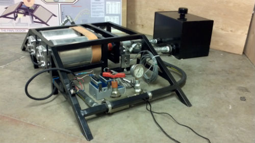
The final concept design includes the following features (Error: Reference source not found):
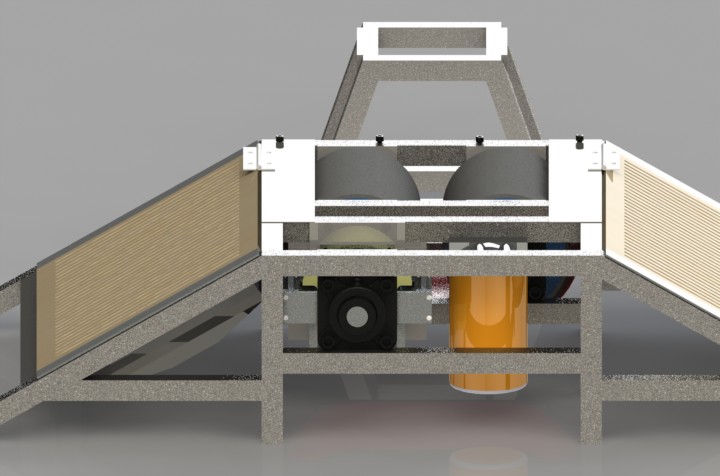
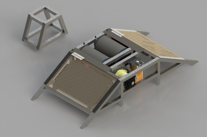
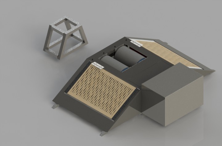
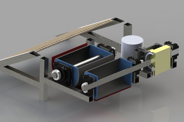
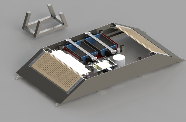
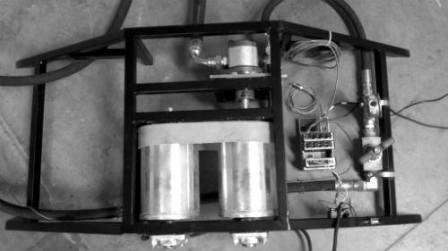
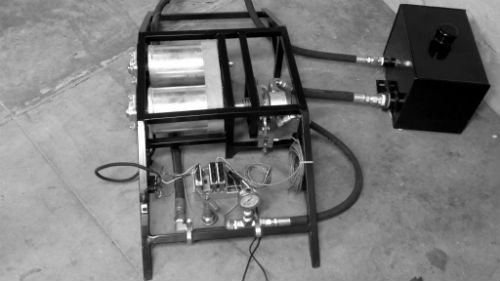
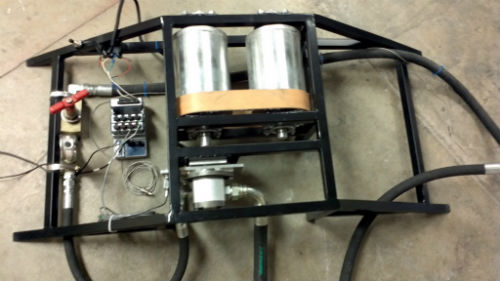
The final design consists of three subsystems, the mechanical system, the hydraulic system, and the data acquisition system. The mechanical system includes the frame, the rollers, and the mechanism that enables the accurate measurement of torque. The hydraulic system is a hydraulic circuit that comprises a pump, a needle valve, strainer, heat exchanger, and reservoir. Its purpose is to load the engine. The DAQ system processes the rpm and torque readings and will control the load on the engine.
The vehicle’s drive wheel will be placed on the roller assembly, while the rest of the vehicle is tied down to other blocks. One of the rollers is connected to the hydraulic pump through its shaft by a shaft coupling. When the vehicle applies power to the drive wheel, the hydraulic system places a load onto the vehicle. This load is meant to simulate the vehicle’s acceleration and road load under operating conditions.
The rollers are supported by roller bearings on both sides of each roller. The bearings are mounted to the frame.
The power the vehicle delivers to the drive wheel is computed from the measured torque and the measured rpm. RPM measurements are taken by a hall-effect sensor detecting a set of metal plates attached to the rollers. The signals are fed to the control system, where it is processed to give a power reading.
The torque measurements are obtained from the torque the pump exerts onto the rollers. The pump and the pump mount are constrained such that it can “free rotate” about its shaft axis. A load cell is attached to the pump mount such that it constrains the “free rotation” of the pump. This way, the force transducer resists all of the torque provided by the pump. The torque is the calculated by multiplying the force reading from the transducer by its distance to the shaft axis. The load on the engine is controlled by restricting the flow of hydraulic fluid through the hydraulic system.
One of the subsystems of the chassis dynamometer is the loading subsystem that will simulate normal road conditions by providing a load to the vehicle’s wheel. A generic hydraulic system was developed to show how the loading system would operate. Figure shows the integration of all hydraulic components into a hydraulic circuit. The hydraulic circuit consists of a hydraulic gear pump (1), a pressure gauge (2), a flow control valve (3), a temperature sensor (4), a strainer (5), and a reservoir (6).
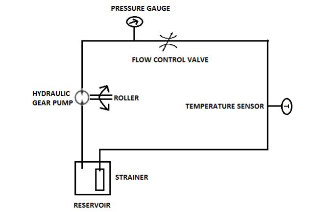
Figure 1: Generic hydraulic system that will simulate road conditions.
Figure 1 shows the basic operation of the hydraulic system, in the correct sequence, at maximum operating conditions.
In addition to the main hydraulic components, a pressure gauge upstream of the flow control valve will allow the user to monitor the pressure. A temperature gauge downstream of the flow control valve will monitor temperature to make sure that temperature stays below 150ᵒF.
The operating conditions of CPSMV’s vehicles were analyzed before specifying each hydraulic component. Table 6 shows the assumed maximum operating conditions for the current vehicles of CPSMV.
Table 6: Performance characteristics for Capax and Prototype vehicles.
Specification | Capax | Prototype |
Max Power (HP) | 3.0 | 2.4 |
Peak Toque (lbf-ft) | 3.5 | 2.0 |
Max Speed (mph) | 35 | 40 |
Total weight with driver (lbf) | 450 | 339 |
Using the maximum speed of 40 mph as the limiting factor, we determine that the maximum rotational speed of the rollers is 2244 rpm. Since the rollers will be directly coupled with the pump’s shaft, we can say that the maximum speed the gear pump will operate at is 2244 rpm also. Next, the required output flow must be calculated from the pump’s operating speed. Utilizing the smallest pump possible (fluid displacement of .40 in^3/rev) in order to achieve the lowest possible output flow, we calculated the actual output flow to be 3.89gpm. In order to calculate the maximum loading required, the maximum weight of the vehicles must be considered. Utilizing 450lbf as the limiting factor, the maximum torque than can be applied to the wheels before slipping occurs is 16lbf-ft. For this calculation a static friction of 1 between tire and rollers was assumed. It was also assumed that there is no slip from the belt connecting the rollers at this load. From the maximum shaft torque of 16lbf-ft, the required pressure loading at the pump’s outlet was calculated to be 3016psi. The maximum fluid horsepower developed, which can be calculated from the pressure and flow rate, turns out to be 6.85HP. This translates heat generation of 17,729 Btu/hr.
An important consideration of hydraulic systems is heat generation. Flow restrictions create a pressure differential and also increase fluid temperature significantly. Maximum working fluid temperature should not exceed 150ᵒF. Operating temperatures above 150ᵒF will change the properties of the hydraulic fluid. This could lead to oxidation of the oil, deterioration of seals, and changes in viscosity. A drastic change in viscosity could lead to metal-to-metal contact and damage would occur. The greatest pressure drop in the hydraulic system is across the flow control valve. The equivalent heat generation at this location is of 17,729 Btu/hr, or 6.85HP at continuous operation. However, since the dyno will only be operating at two minute intervals, the operating heat generation that the dyno will see is only 590 Btu/hr.
Table 1 shows the total heat generated by the system. A total of 9.98HP is produced by the losses in the system. The reservoir alone is only able to dissipate 759.23Btu/hr, or 0.298HP. A heat exchanger with a dissipation capacity of 35,897.4 Btu/hr, or 14HP was used in order to keep fluid temperature under 150ᵒF.
Table 1: Total heat generated by system.
Component | Heat Generated (Btu/hr) | (HP) |
Pump outlet | 17420 | 6.85 |
Needle Valve | 200 | .079 |
Filter | 109 | 0.04 |
Total | 17729 | 6.97 |
Total at Operating Conditions | 590 | 0.23 |
All of the frame and roller components are structurally sound for the intended loading.
The frame has yield safety factor of approximately 5 and a maximum deflection of 0.019 inches. This was found by assuming a vehicle and driver weight of 600 lbf. The weight is equally distributed onto the two rollers, which are supported by two bearings. Each side of the frame sees 300 lbf of loading. Since the structure is statically indeterminate, the problem was simplified by removing the bottom bearing flange support beam. This makes the analysis analogous to a beam supported on two ends. The 1” roller bearings will support a maximum load of 150 lbf. Each bearing is rated to for 500 lbf for a dynamic radial load. With the stresses induced by the vertical load and the torque, the one-inch roller shaft has a yield safety factor of 4 with maximum designed loading conditions. This was calculated by applying a 150 lbf shear force and adding an 30 ft lb torque. The pump mount was analyzed as a cantilevered beam with a point load attached to the end. This effectively represents the anchoring force of the torque transducer. This part has yield safety factor of 3.6 and a maximum deflection of 0.015 inches. This was found by assuming a 30ft-lb torque on the pump shaft.
Material, geometry and component selection for the dynamometer was determined based on structural integrity, assembly time, and cost (Table 2).
The frame needed to be welded together and have flat surfaces to mount bearings and hydraulic components to. The A513 steel square tubing met those requirements and was also a low cost material. Even though a low weight was a requirement and a thinner wall tube, 0.035”, could have been used, we felt that due to time limitations, we did not have time to TIG weld the thin walled tubes, so a thicker 0.065” wall thickness was chosen. The thicker wall tube allows us to MIG weld the frame together. The bearing flange mount plates needed to be welded to the frame, so a similar steel was chosen.
The pump mount needs to be CNC machined, so we chose to make it out of 6061-T6 aluminum. This material is cost effective, strong enough for its application, and easy to machine. The bearings were selected based on the shaft sizes and expected loads. The housed bearings, McMaster part 6494K330 was selected to support the roller shaft because it was the lowest cost housed bearing that met the load and shaft diameter requirements. We decided to use housed bearings because they are easy to install onto the frame. A custom bearing mount was not required. The 2.5” inner diameter bearing part used to support the pump mount was selected because it was the cheapest bearing that met the dimensional requirements.
Geometry selection:
The roller diameter of 6 inches was decided because the rotation rate of at a surface speed of 40 mph worked well to drive the selected hydraulic pump. The 40 mph surface speed is the maximum vehicle speed our dyno is designed to simulate. The roller length of 8.5 inches was specified because it gives clearance to the widest tire of 6 inches that the dyno is designed to work with.
Table 2: Material selection for frame.
Component | Material | Justification |
Frame | ASTM A513 1” 0.065 WT square tube | Low price, good weldability, sufficient strength |
Bearing Flange Mount | 1018 Steel 0.125 plate | Low price, good weldability, sufficient strength |
Pump Mount | 6061-T6 1.25” aluminum plate | Low price, good machinability |
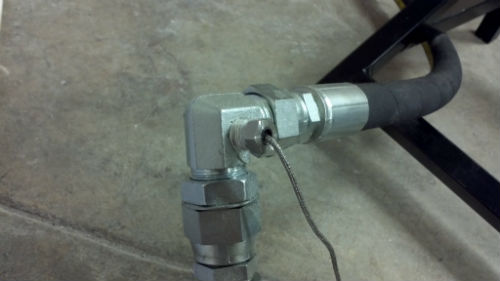
On the dynamometer three temperature sensors, a speed sensor, and a load cell are used to gather data. The power is calculated by P=ωF. The rotational speed is measured by the speed sensor and the force is measured by a load cell. A Cherry geartooth speed sensor was chosen for simplicity and its rugged design. It is easily mounted with an adjustable housing. It is also immune to rotational misalignment, which allows for mounting inaccuracies. The housing is hard coated anodized aluminum. The sensor can operate at 4.5 to 24 volts DC as shown in the appendix, which works with both of the data acquisition systems the team was looking at. The data acquisition system was originally going to be selected according to the projects minimal budget, but the project has since been sponsored by National Instruments Corporation®. The hall-effect geartooth sensor senses the motion of ferrous geartooth targets. The threads on the aluminum housing of the sensor will allow for easy adjustment. It will be mounted very close to the rollers on the dynamometer. A ferrous material (steel) screw is drilled into a roller. Using a digital input/output on the DAQ, every time the ferrous material passes the sensor, a pulse will be displayed in LabView®. From these pulses and the roller diameter of the system LabView converts the signal into revolutions per minuets.
For the temperature sensors, Omega® RTD pipe plug probe sensors were chosen. An RTD was chosen because it is much more accurate and linear than thermocouples. RTD probes are made for high pressure vessel applications and are rated for up to 2,500 psi. While the maximum pressure in the dynamometer will be 3,000psi near the pump, the temperature sensors will be in the reservoir and near the heat exchanger where the pressure will be minimal. The mounting threads on the probes allow for a simple attachment point at a T in the hose or to be screwed into the side of the reservoir. The RTD probes have a maximum of 450 degrees Fahrenheit which is well above the maximum temperature of the system of 150 degrees Fahrenheit. The force measurement is taken by an S-beam load cell. The load cell was chosen because it was donated by Dr. Joseph Mello and it met the specifications of 100lb from the max torque of 360 lbin in the appendix calculations.
The data acquisition system is a modular compactDAQ donated by the National Instruments Corporation®. The DAQ was selected for our specifications and the sensor specifications. Expansion of the data acquisition is much easier with the 2-24 bit analog input modules. The analog input comes with USB, Ethernet, and wireless connectivity. It also has built in quarter, half, and full-bridge support. A built in current and voltage excitation is perfect for strain gages and load cells. However the excitation for the speed sensor is three 9 volt batteries in series. This is because the maximum excitation voltage the analog module can provide is four volts. RTD measurements are also supported by the analog inputs. The load cell and the temperature sensors will use 1 channel each and each analog module has 4 channels. Therefore there will be 4-6 channels for additional analog sensors, depending on how many temperature sensors are used. The sinking digital input module has 8 channels and is 12 to 24 V logic. The speed sensor will use one digital channel on the digital module. Further calibration and filters are needed as the torque measurement has a lot of noise, as shown in the testing results screen shot (Figure 17).
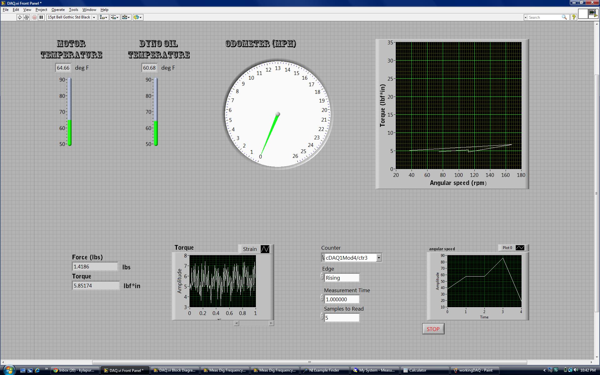
Figure 17: Screen Shot of LabView During Testing of Dyno
LabView allowed for easy manipulation of the data. It was straightforward and simple to use. One member on the team out of the four people started with very little experience with LabView, while the others (including the one who picked the snsors and did the LabView) started with none.The compact DAQ seemlessly worked with the sensors and LabView. With the compact DAQ less equipment was needed as the analog module contained excitation voltage and amplifiers for the load cell.