- Subscribe to RSS Feed
- Mark Topic as New
- Mark Topic as Read
- Float this Topic for Current User
- Bookmark
- Subscribe
- Mute
- Printer Friendly Page
FPGA-based Hardware-in-the-loop Testing for MW-Level Wind Turbine Converter Controllers
06-03-2015 03:32 AM
- Mark as New
- Bookmark
- Subscribe
- Mute
- Subscribe to RSS Feed
- Permalink
- Report to a Moderator
Application Abstract:
This article introduces an hardware-in-the-loop (HIL) application for a power electronic controller(doubly-fed induction generator converter controller). The challenge of power electronics real-time simulation is that it requires a very small step size (microsecond level). ModelingTech (info@modeling-tech.com, www.modeling-tech.com) leverages NI FPGA hardware and Software to achieve such small step size (2.5 us) real-time simulation and provide a HIL system to testing Envision Energy's real wind turbine converter controllers.
Envision Energy Introduction:
Envision Energy is one of the biggest wind turbine vendors. With the world’s most stable and reliable system integrated with transmission chains and components, Envision Energy’s 4 MW offshore turbine is specially designed for the offshore wind power. By applying its techniques, systems, and algorithms, along with its first-ever smart control techniques, advanced gauging techniques, specialized data analysis system, active performance controls, and decision algorithms for reliability, Envision Energy has improved the power generation rate of its turbine products by 20% compared to products of the same type, and has become the first choice for developing offshore wind power in China (above information is from Envision website www.envision-energy.net ).
HIL Requirements: Faulty Condition Test and On-Site Conditions Reproduction:
The R&D and Testing Departments of Envision want to use a HIL platform to simulate a real double-fed induction generator (DFIG) system, so that they could test the operation of converter controller under various conditions, especially the power grid fault cases. On the other hand, due to the fact that the operation of wind turbine system is greatly influenced by uncontrollable meteorological conditions, by using this HIL platform, the R&D and Testing Department could reproduce various on-site working conditions in the lab and test the operation of their wind turbine.
DFIG System Introduction:
Double-fed induction generator is a mainstream wind-turbine generator. The advantage of the DFIG system is that the power transferred though the power electronic converter is only a portion of the total wind turbine system power, this could lower the cost of the power electronic components.
The controller of DFIG controls a pair of back to back PWM converters to control the frequency and amplitude of the rotor voltage, so the whole system can achieve a variable speed constant frequency operation and active-reactive power decoupled control.

DFIG Real-time Simulation Challenges:
Double-fed system is a classical power electronic system. Unlike real-time simulation for traditional power grid system, the power electronic system contains fast switching components. For better simulation precision of the power electronic system, a very small simulation step size(microsecond level) is required. ModelingTech leverages FPGA technology to realize the DFIG real-time simulation.
The DFIG models are different under different working conditions (before and after connecting the generator stator to the power grid). Common off-line simulation software, such as Simulink/SimPowerSystems, could only support grid-tied generator model (The generator is modeled as the current source). This kind of model couldn’t simulate the whole process that DFIG system no-load running first and then connecting to the grid. ModelingTech is capable of providing a DFIG system model supporting both DFIG no-load excitation mode and grid-tied power generation mode, helping users to simulate the whole process.
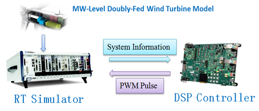
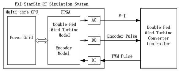
HIL Solution Based on StarSim FPGA and PXI Platform
The hardware-in-the-loop system architecture is as below:
The following pictures are the field photos of the DFIG HIL system. The picture left below is the front view of the cabinet. The picture right below is the rear view of the cabinet, the PXI system is running the StarSim DFIG model.

The picture as below is the host user interface of the real-time simulation system. Here, the system is in the no-load running mode. The controller controls the rotor excitation current and enables DFIG to meet the grid connection condition (the amplitude, phase and frequency of stator voltage are the same as those of power grid). In the stator voltage waveform graph, the generator stator voltage(blue) is becoming gradually in line with the grid side voltage(red).

Host User Interface of Real-time Simulation System
