- Document History
- Subscribe to RSS Feed
- Mark as New
- Mark as Read
- Bookmark
- Subscribe
- Printer Friendly Page
- Report to a Moderator
- Subscribe to RSS Feed
- Mark as New
- Mark as Read
- Bookmark
- Subscribe
- Printer Friendly Page
- Report to a Moderator
Course Linkage: Linear Circuit Analysis >> Resistive Circuits >> Series and Parallel Resistors
Measurement Techniques: ELVISmx DMM (ohmmeter)
<hr width=”75%”>Introduction
Overview: Two previous myDAQ mini-labs (Equivalent Resistance I – Seriesand Equivalent Resistance II – Parallel) explored resistor circuits that were either entirely series or entirely parallel. Practical circuits generally contain both series and parallel combinations. Reducing these circuits to a single equivalent resistance is an important analysis skill.
Objectives: In this mini-lab you will:
- Learn about resistor color codes
- Measure the resistance of individual resistors
- Compare measured resistance to nominal value
- Predict the equivalent resistance of mixed series-parallel-connected resistors
- Compare measured equivalent resistance to expected values
Equipment
- NI myDAQ
- Breadboard
- Connecting wire
- Resistors, ¼-W 5% carbon film: 10K (two), 33K (two), 47K (two)
Deliverables
- Submit your work in the form of a homework set problem or lab notebook entry according to the requirements of your instructor
- Submit your work for each underlined boldface item, and clearly label the item with its section letter and task number
A. Experience series-parallel resistors by measurement:
NOTE: Proceed directly to Step 10 if you have already completed the myDAQ mini-lab Equivalent Resistance I – Seriesand your breadboard still contains the same resistors that you measured earlier; you will need those measurements for this mini-lab.
- Study the short article Resistor Color Codesto learn how to read the nominal value encoded in the color bands that encircle a resistor. For example, the 10K resistor has the color code “orange-orange-orange” = 33 x 103 = 33 kW.
- Record the color bands for the 10K and 47K resistors.
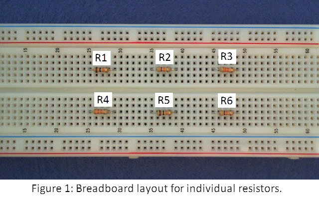
- Place the six resistors on your breadboard as shown in Figure 1. Use the same hole spacing to match the wiring that will be added later.
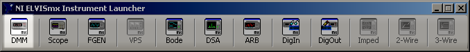
- Start the ELVISmx Instrument Launcher and click “DMM.” Choose the ohmmeter instrument (the “ohm” symbol, capital omega), select autoranging (choose “Auto” for “Mode”) and click the green “Run” button:
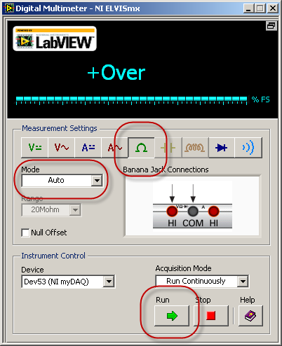
- Connect the DMM probes to the ohmmeter side (red volt-ohm and black COM jacks) as shown on the ELVISmx DMM “Banana Jack Connections” graphic.
- Touch the DMM probe tips together to ensure that the ohmmeter properly reads zero or at most a fraction of an ohm. The probe cables have negligible resistance compared to the resistors used in this mini-lab.
- Measure and record the resistance of each of the resistors R1 through R6.
- Create a data table with four columns: resistor label, nominal value (i.e., the value indicated by the color code), measured value, and percentage difference from nominal. Calculate the last column as ((Rmeasured – Rnominal)/Rnominal) x 100%.
- Report the largest percentage difference and whether or not it falls within 5% of the nominal value; this is the significance of the gold 5% tolerance band on the resistor.
- Connect the resistors as shown in Figure 2 (click the image to see higher resolution):

- Measure and record the resistance between terminals A and B.
- Rewire your breadboard to connect the resistors as shown in Figure 3:
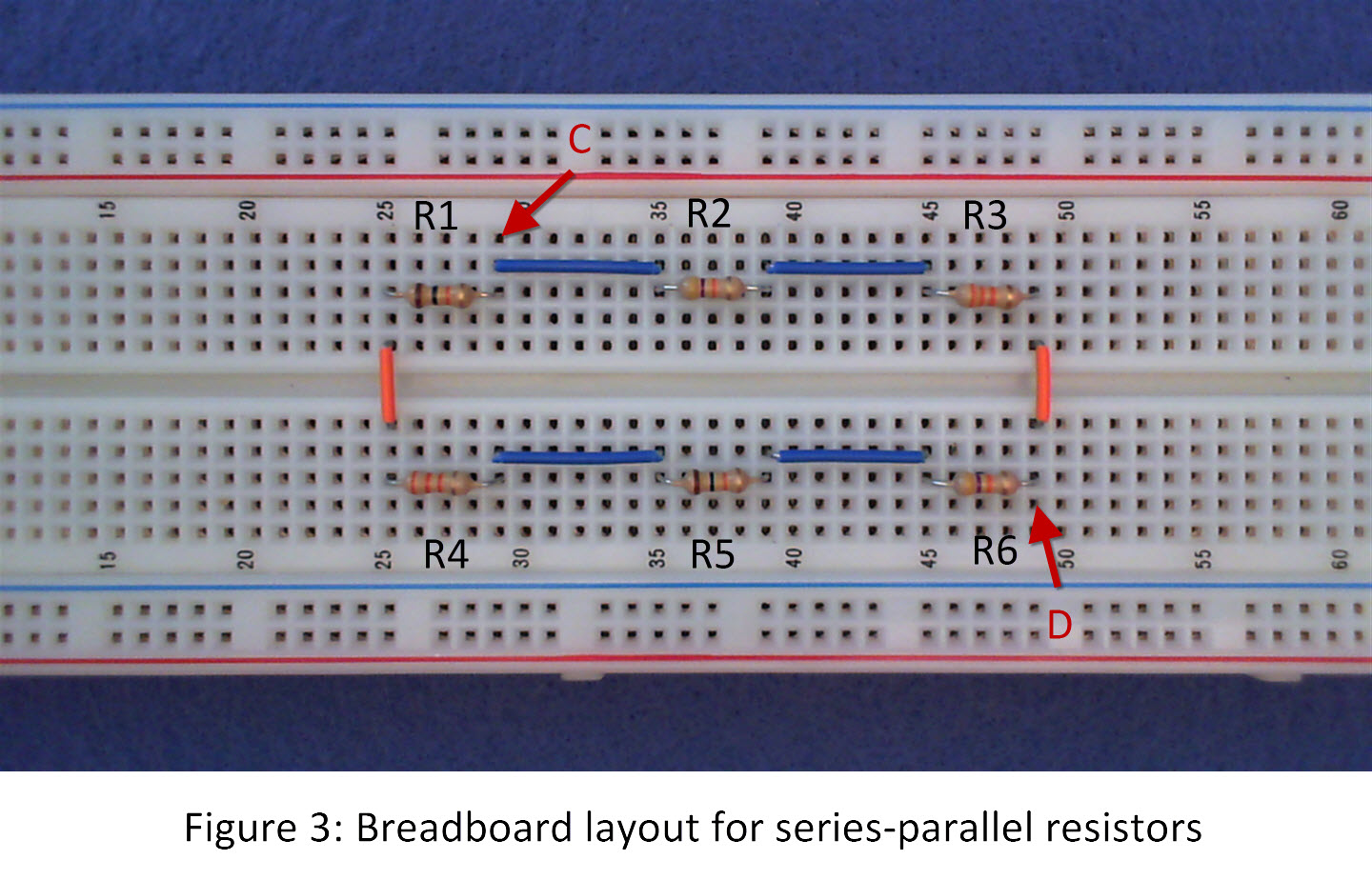
- Measure and record the resistance between terminals C and D.
B. Learn the underlying principles:
The following video tutorial describes how to calculate the equivalent resistance of the two circuits you measured in the previous section:
C. Connect the principles to your measurements:
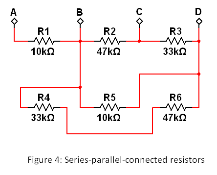
- Rewire your breadboard to match the circuit shown in Figure 4:
- Draw a sketch of your new breadboard layout.
- Calculate the equivalent resistance between the following terminal pairs using your measured resistance values for R1 through R6: A-B, B-C, C-D, and A-D.
- Measure and record the resistance between the same terminal pairs: A-B, B-C, C-D, and A-D.
- Calculate the percentage difference between your measured value and your calculated value.
- Report the maximum percentage difference between your calculated and measured values. If the difference is more than 1%, review your wiring and calculations and make corrections as necessary.
D. Build your intuition:
- Respond: In which of the four terminal pairs from the previous section does the resistor R1 actually not contribute to the effective resistance? Explain why.
- Draw a circuit based on the six resistors R1 through R6 (use the same layout as Figure 1) that has an equivalent resistance of 45 kW. Hint: The parallel combination of two equal-valued resistors has half the resistance.
For more information
