- Document History
- Subscribe to RSS Feed
- Mark as New
- Mark as Read
- Bookmark
- Subscribe
- Printer Friendly Page
- Report to a Moderator
- Subscribe to RSS Feed
- Mark as New
- Mark as Read
- Bookmark
- Subscribe
- Printer Friendly Page
- Report to a Moderator
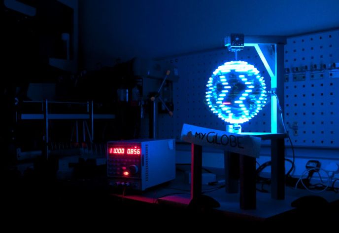
myGlobe: Making 3D Images in Thin Air
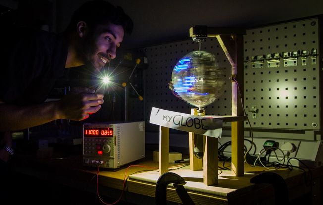
To be able to draw 3D images in thin air, myGlobe leverages the persistence of vision quirk of human vision. When the human eye is subjected to multiple images in fast succession it cannot differentiate between them and so they merge into one continuous image. The human eye registers any discrete sequences that happen faster than 20 Hz as a continuous image.
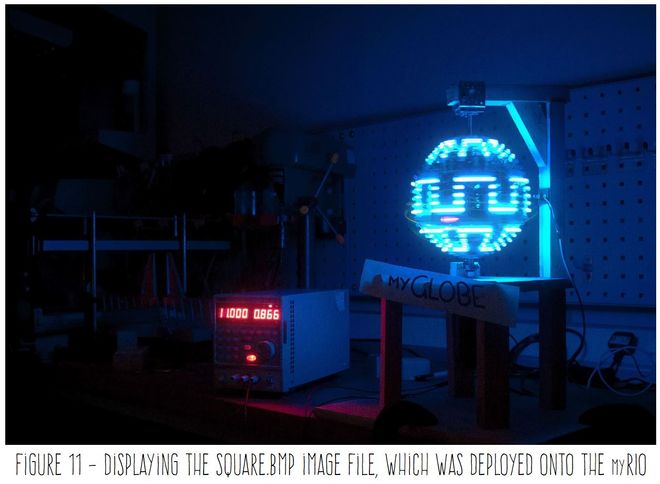
For myGlobe, I'm rotating a curved array of LEDs (along with the myRIO controller and associated circuitry) around an axis-point, with the help of a small motor. The LEDs array flashes with different patterns in quick succession, which fools your eye into seeing a continuous image. For example, I have used myGlobe to display a world map, funky patterns and many emojis. But, of course, you can easily add other designs to your liking.
Additionally, if you are a better artist than me, you could easily create a series of images, which the myRIO can cycle-through to create glowing, 3D animations!
About the Developer.
My name is Viktor Pankov and I'm an Electrical and Electronic Engineering student at the University of Manchester. As part of my industrial placement at National Instruments I was given a week to design and build a cool gadget inspired by the Maker Movement.
How to Make Your Own.
The 3 parts of this design are:
- Mechanical build of the supporting wooden structure and stable rotating axis;
- Electronic circuit that controls and powers the flashing ring of 25 LEDs and measurement of rotation speed;
- Programming the myRIO to output the correct pattern on the LEDs.
The myRIO must feed a predetermined pattern of binary pixels to the 25 LEDs. The pattern must be synchronized with the ring’s rotation and triggered by the IR LED.
The project is difficult to pull off and requires access to power tools.
Making the LED Ring.
For the LED ring, I cut out a 22-mm wide and 2 mm tick ring out of an old paint bucket with a diameter of 20 cm. To drill holes for the LEDs and afterwards mount the ring onto the whole assembly I cut it in one place. Afterwards I clamped the ring down to a table to straighten it out and then used a 4.5mm drill bit to drill 25 holes with 6mm spacing between each hole. With 4.5mm holes I securely press fit my 5mm LEDs with no glue.
The LEDs.
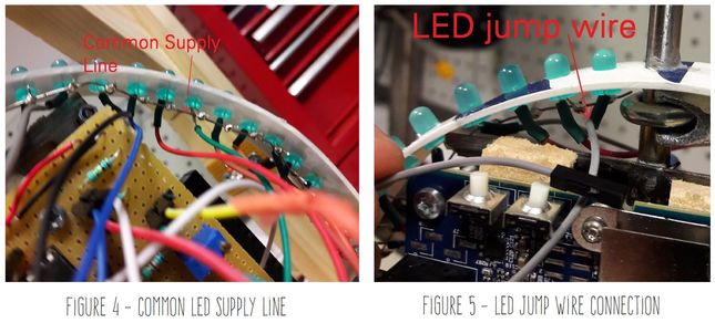
I used female jumper wires to connect the LEDs to the circuit board. The negative leg of each LED is soldered to the female jump lead. This approach makes maintenance much easier. The positive leg of all the LEDS is connected to a common supply line (See Figure 4), while all the negative legs are connected to the circuit board (See Figure 5). My circuit limits the path to ground to control when LEDs are on.
Measuring Rotation Speed and Precise Image Timing.
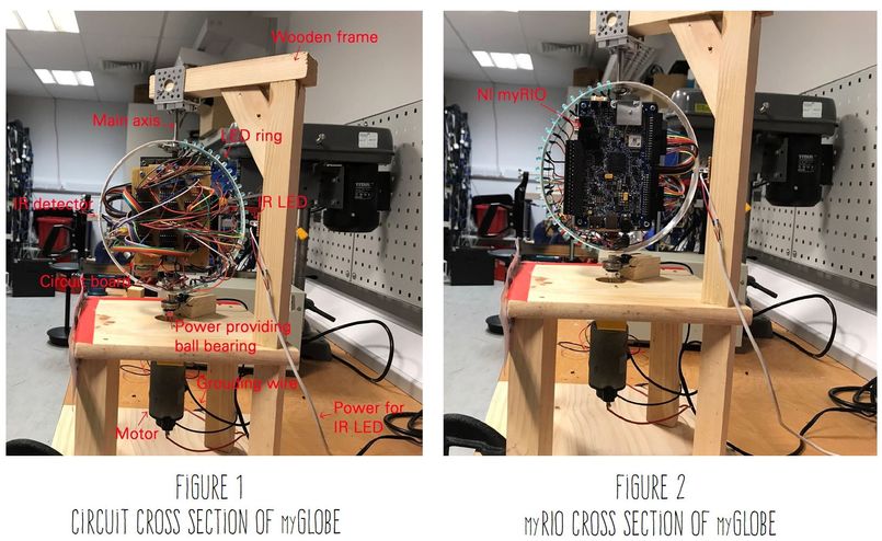
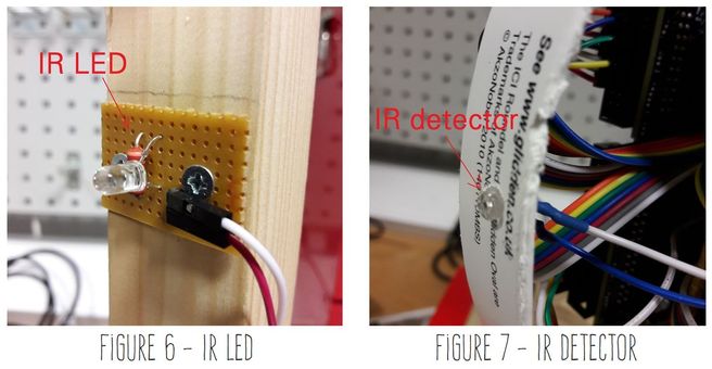
For myGlobe to generate a stable image the pattern on the LEDs must always begin at the same instance. The purpose of the IR detector on the ring is to detect each revolution by registering a digital edge each time it moves past the IR LED on the wooden frame. The frequency of rotation is calculated based on the registered digital edges in a given amount of time. Figure 6 shows the IR LED and Figure 7 shows how the IR detector is secured to the ring.
Providing Power.
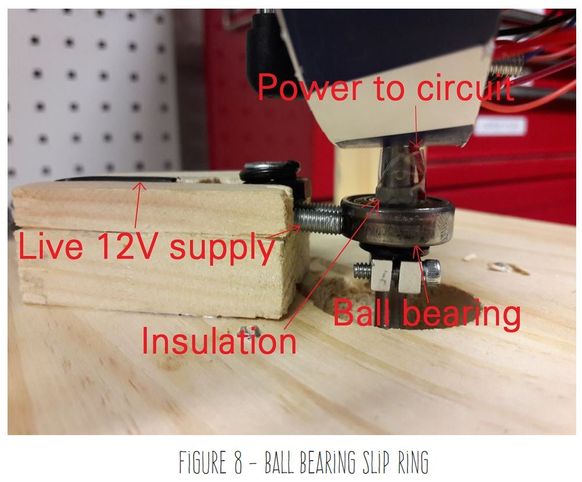
I’m providing power to the whole rotating assembly using a homemade slip ring. The configuration features a ball bearing, which is insulated from the main rotating shaft by cable insulation. There is cable that runs from the circuit board to the inside ring of the ball bearing. I’ve ensure a continues power supply by firmly pressing a U bracket to the outside ring of the ball bearing. The power circuit is grounded through the housing of the motor. Figure 8 below provides further detail.
Circuitry.
The electronic circuit is design for the following tasks:
- Provide power to the myRIO at 12V;
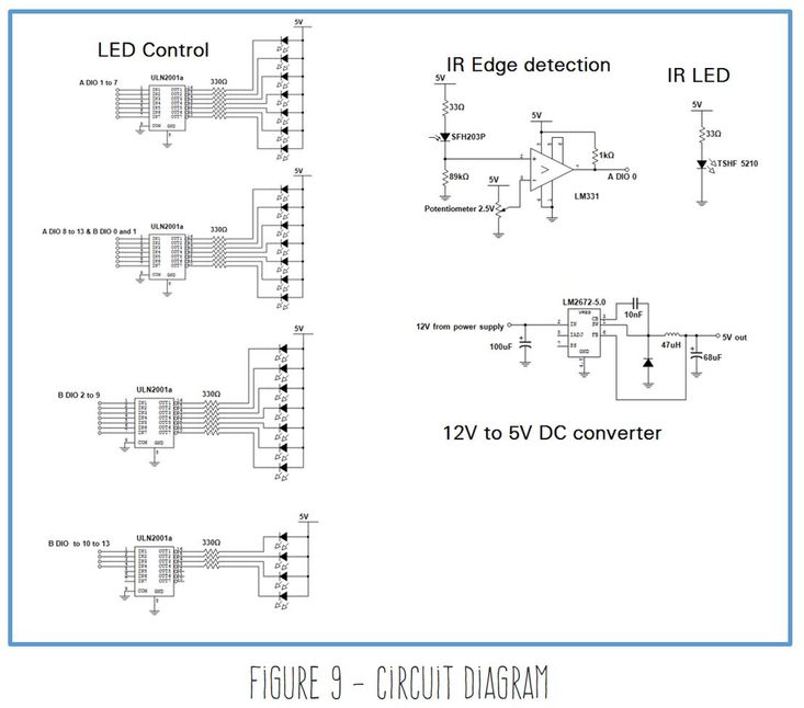
- Control the 25 LEDs using individual DIO lines of the A and B connectors of the myRIO;
- Step down voltage from 12V to 5V to power the 25 LEDs;
- Register ring revolutions using the digital edges generated by the IR LED and IR detector.
Figure 9 shows the pin outs and connections for the circuit.
myRIO Control Program.
The attached LabVIEW VIs run on the Linux Real-time processor of the myRIO. The program registers rotations, calculates the frequency of revolution and feeds the various light patterns to the LEDs
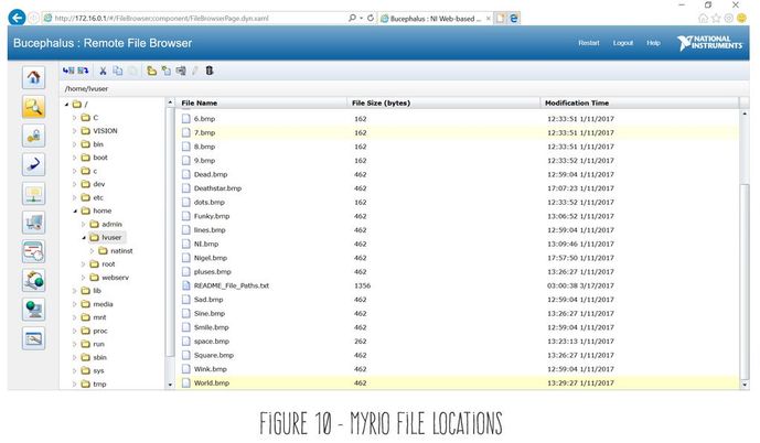
You will also find a zip containing all the bitmaps used in create the images. The files should be stored in /home/lvuser location on the myRIO. (Figure 10)
Requirements.
SW:
- LabVIEW 2017
- LabVIEW Real Time
- LabVIEW FPGA
- LabVIEW myRIO toolkit
HW:
- NI myRIO
- 25 x blue LEDs
- 25 x 330 Ω resistors
- 2 x 33 Ω resistors
- 1 x 89kΩ resistors
- 1 x 1kΩ resistors
- 4 x ULN2001a Darlington transistor pairs
- 1 x SFH203P IR detector
- 1 x TSHF 5210 IR LED
- 1 x LM331 Amplifier
- 1 x LM2672-5.0
- High current diode
- 1 x 100 uF capacitor
- 1 x 10nF capacitor
- 1 x 47 uH inductor
- 1 x 68 uF capacitor
- 10cm x 10cm piece of stripboard
- Loads of male header pins
- Loads of female to female jumper leads
- myRIO power plug
- Loads of single core wire
- 12V 5A 30W DC motor
- 6mm 30cm mounting shaft
- Shaft coupling for motor and mounting shaft
- PWM motor controller/ variable power supply
- Heat shrink
- Soldering iron
- Solder
- Wood to make the supporting table
- 2 x Ball bearings with internal 6mm diameter
- Metal brackets to secure shaft to wooden structure
- Metal brackets to weld on to main shaft
- Welder
- M3 x 20mm screws
- M3 nylon locking nuts
- Super glue
Useful Resources.
Hacker’s Handbook: Compendium of Maker Projects
Preparing Future Innovators With the NI LabVIEW RIO Architecture
