From Friday, April 19th (11:00 PM CDT) through Saturday, April 20th (2:00 PM CDT), 2024, ni.com will undergo system upgrades that may result in temporary service interruption.
We appreciate your patience as we improve our online experience.
From Friday, April 19th (11:00 PM CDT) through Saturday, April 20th (2:00 PM CDT), 2024, ni.com will undergo system upgrades that may result in temporary service interruption.
We appreciate your patience as we improve our online experience.
08-15-2013 01:53 AM
 | This document was created for the myRIO Balancing Robot Project https://decibel.ni.com/content/groups/myrio-balancing-robot |  |
The subject of this paper is about how to implement the gyro sensor on myRIO balancing robot. The goal of using the gyro sensor is to help the accelerometer in the myRIO to detect fine angle changes. Many mecatronics systems work with that combination of sensors in order to do the most fine control as possible.
![]()
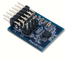
--------- Picture 1 PmodGYRO -----------
A gyro is a device which reacts to angle variations. For our application, we used the L3G4200D sensor mounted on the module PmGYRO it allows knowing information’s about the 3 axis (X, Y, Z). This module use a standard 12 pins connection and can communicate by using a I2C or SPI protocol. On the board, a pull-up resistor on the pin CS of the chip keeps the device on I2C mode unless the pin is driven low by the master device in order to communicate in SPI mode.
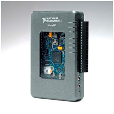
----------- Picture 3 myRIO --------------
This device will allow us to know if the robot is falling down or not. As you know, our system is at the equilibrium position when the body is at 90° to the floor. If the robot is falling, the gyro will detect the angle changes and it will send it to the myRIO so we will be able to maintain our robot at the equilibrium. In this first part, we are going to interest our self on the data communication protocol between the gyro and the master device.
As you know, the device we use can communicate data by two ways:
At rhe begining of the prooject, we chose to work with I2C protocol because it’s easier to work with, and it use less pins than the SPI on myRIO Board.
I2C is a synchronous data communication protocol it allow to share data with multiple devices according to the master/slave principle. Actually, when you want to communicate with multiple devices, you can only have one writer. That’s why, in I2C protocol, you have one master devices and slaves devices. The master device will allow other devices to read or write data on the I2C bus. The I2C bus is composed of two wires:
Each I2C device has a different physical address in order to communicate easily. In an I2C communication, the master device has to speak the first in order to allow a slave device to work. The I2C frame is the following:
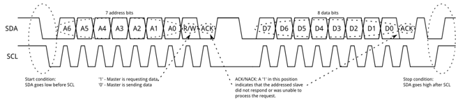
------------------------------------------------------------- Picture 3 I2C protocol -------------------------------------------------------------
In order to implement the gyro sensor to our robot, we need to communicate with by using LabVIEW. In this way, we used a NI UBS-8452 device it can useI 2C communcation.

Picture 4 Ni USB 8452 & PmodGYRO
The picture 4 show the applications we done in order to communicate with the gyro sensor. The sensor only needs four wires to be ready to communicate.
Usually, an I2C driver need pull-up resistors on SDA and SCL lines. In this case, the NI USB-8452 has internal pull-up you can chose to activate or not.
Before beginning to code, we need to know some information about the sensor:
You can find those information’s in the L3G4200D and on PmodGYRO datasheets.
In this case, the physical address of our component is 0x69. We want to measure angle changes on the robot, so we need to acquire values really fast. So, we’ll need to use those following registers:
Register | Address | Value | Description |
CTRL_REG1 | 0x20 | 0x0F | Enable X, Y, Z and Normal power down mode |
CTRL_REG2 | 0x21 | 0x00 | Normal mode filtering |
CTRL_REG3 | 0x22 | 0x00 | All disable |
CTRL_REG4 | 0x23 | 0x80 | Output registers not update until MSB and LSB reading |
CTRL_REG5 | 0x24 | 0x00 | All disable |
OUT_X_L | 28 | - | X-axis angular data (Less Significant BYTE) |
OUT_X_H | 29 | - | X-axis angular data (Most Significant BYTE) |
OUT_Y_L | 2A | - | Y-axis angular data (Less Significant BYTE) |
OUT_Y_H | 2B | - | Y-axis angular data (Most Significant BYTE) |
OUT_Z_L | 2C | - | Z-axis angular data (Less Significant BYTE) |
OUT_Z_H | 2D | - | Z-axis angular data (Most Significant BYTE) |
Now we have all hardware information we can start coding with LabVIEW. With the USB-8452, we can use the I2C functions palette. On the following picture, you can found our application bloc diagram.
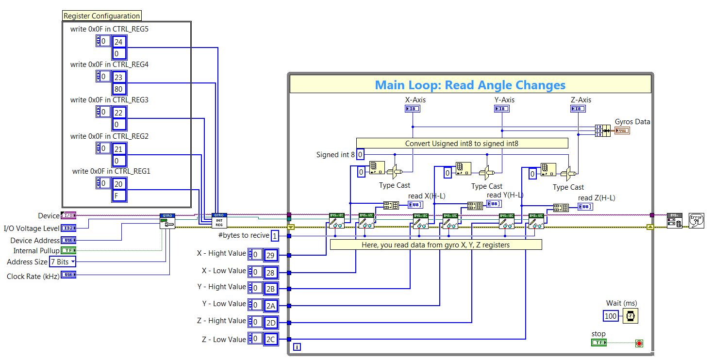
--------------------------------------------------------------------------------------------------- Picture 5 Gyro.vi block diagram ---------------------------------------------------------------------------------------------------
This diagram can be read from the left to the right according the error cluster which one control the data flow. At first, we find this function:
------------- Picture 6 Hardware Setup.vi -------------
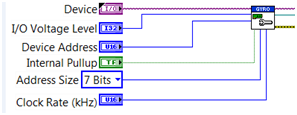
This subVI allows configuring the hardware. We set the NI device we want to work with, the power supply level for our I2C device, his address, activate the internal pull-up, the size of the address, and the SCL rate. But how is this VI working?
The following picture represents the internal view of hardware setup.vi subVI:
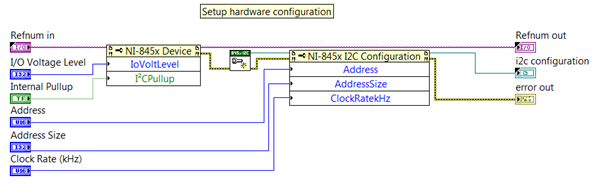
-------------------------------------------- Picture 7 Hardware Setup SubVI ------------------------------------------
On this VI, we can found two property nodes and an I2C function. The first property node is to setup how the NI USB-8452 will drive the gyro. Then, you have Create New I2C.vi which one allows opening an I2C communication. To finish, the last property node is to configure the communication by setting up the address, the address size, and the SCL clock rate.
The following graph shows the first I2C frame:
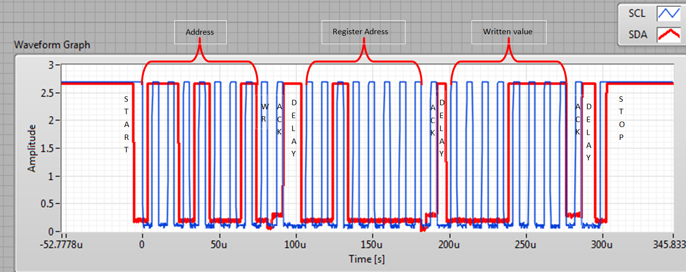
-------------------------------------------------------------------------------------- Picture 8 I2C frame --------------------------------------------------------------------------------------------
Let’s go back on the main VI (GYRO.vi) diagram in order to see the next function:
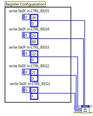
----------------- Picture 9 INIT_REG.vi--------------------
This subVI allows configuring registers. Here we set all registers at the Table 1 values. This VI is composed with five I2C write functions. Each of this function has an array in input. Those array values are written one by one as you can see on Picture 8.
The next step is the main loop:
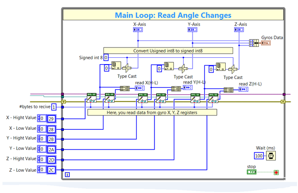
---------------------------------------------- Picture 10 Main Loop---------------------------------------------------------
At the entrance of the loop, we have some array constants they are the output register addresses (Table 1). You can find the “#bytes to receive” constant witch one allow to configure the number of byte to read for one register. In this case, the registers send only one byte. In the loop, we are reading from the sensor the six angle registers and we display them in a graph. The loop iteration rate is 100ms. On the following picture, you can see the front panel on this VI with the graph containing gyro data.
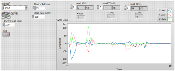
------------------------------------------- Picture 11 GYRO.vi front panel ----------------------------------------------
To finish, we close the I2C communication and we handle errors with those functions

Picture 12 I2C close
This experimentation shows that implementing the gyro sensor with LabVIEW is quite easy. Now we need to adapt this code to the myRIO device and process our read data according the physical model.
Picture 1: https://www.digilentinc.com/Products/Detail.cfm?NavPath=2,401,937&Prod=PMOD-GYRO
Picture 2: http://www.eeweb.com/blog/jim_harrison/national-instruments-myrio-euducational-tool
Picture 3: https://learn.sparkfun.com/tutorials/i2c/all
