- Subscribe to RSS Feed
- Mark Topic as New
- Mark Topic as Read
- Float this Topic for Current User
- Bookmark
- Subscribe
- Mute
- Printer Friendly Page
How to create a 3D Robot with CAD files
08-19-2013 08:01 AM
- Mark as New
- Bookmark
- Subscribe
- Mute
- Subscribe to RSS Feed
- Permalink
- Report to a Moderator
<tr>
<td style="text-align: left;"><img alt="Community Logo.png" class="jive-image" src="https://decibel.ni.com/content/servlet/JiveServlet/downloadImage/102-30641-7-114848/Community+Logo.p..." __jive_id="114848" /></td>
<td style="text-align: center;"><span style="font-size: 8pt;"></span></td>
<td style="text-align: right;"><span style="font-size: 8pt;">This document was created for the<strong> myRIO Balancing Robot Project<br /></strong><a href="https://decibel.ni.com/content/groups/myrio-balancing-robot" _jive_internal="true">https://decibel.ni.com/content/groups/myrio-balancing-robot</a></span></td>
<td style="text-align: right;"><img alt="myBOT.png" class="jive-image" src="https://decibel.ni.com/content/servlet/JiveServlet/downloadImage/102-30641-7-114893/myBOT.png" __jive_id="114893" /></td>
</tr>
</tbody>
</table>
myRIO Balancing Robot - How to create a 3D Robot with CAD files
Overview
This document shows how to import .wrml CAD files and how to process them in order to build a 3D Robot picture.
![]()
Introduction
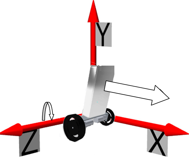
In order to do the User story U-028 “Simulate simple balancing Robot”, we need to build a 3D picture of the robot which allows to be moved in the space. At first, we need to know what parameters can influence the robot to move. To simulate a simple system, the robot only has to translate on the X axis and rotate over the Z axis.
Now, we have to build an object composed by different parts according to the specifications. So the Robot needs to be over a solid surface, that’s why a part of our picture has to represent the floor. The body of our system can rotate over the Z axis and the roads have to translate on X in order to the body’s angle with the floor progressively turn to 0°. So the robot will be composed of two parts (body and chassis).
myBot_Create.VI
This VI allows importing CAD data on LabVIEW and processing them in order to build a 3D picture of the robot. In the following picture you can see the different functions to build this 3D picture.
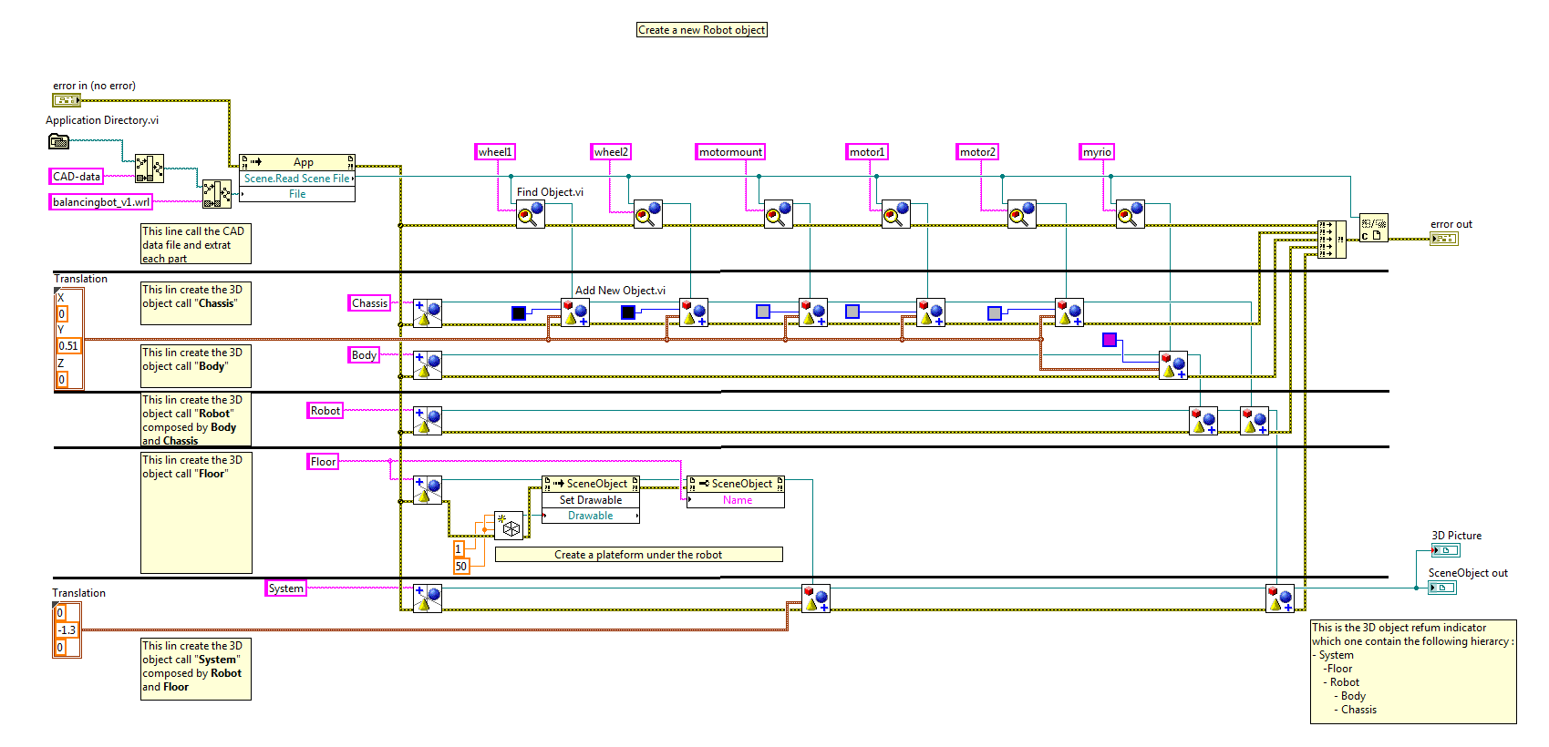
This VI is divided horizontally in 5 rows executing in parallel. The first one allows importing CAD data file and extracting each component as a 3D object.
First line explanation
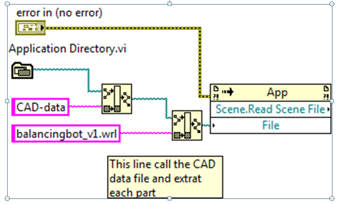
Here, we build a path to our CAD data in order to open them as an object.
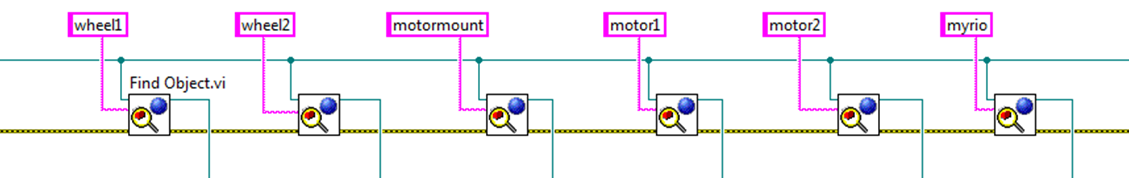
Then, we extract each part of the CAD file Robot as 3D object in order to build subparts.

At the end of the line, according the merge error function, the program will wait for all the lines finish their tasks and will close the CAD file with the Close Reference function.
Second line explanation
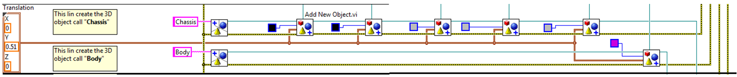
This line is separated in two subparts corresponding to the point 1 of this document. For the chassis line, we create an object called “Chassis” and we add to that object two wheels, two motors, and the motor mount extracted from the CAD file. For the body’s line, the process is the same. We create the object called “Body” and we add to him the myRIO extracted from CAD file.
Third line explanation

In this line, we create the object called “Robot” and we add “Chassis” and “body” objects.
Fourth line explanation
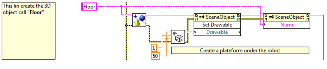
In this line we create an object called “Floor”. Then we draw a 3D rectangular surface which is added to "Floor".
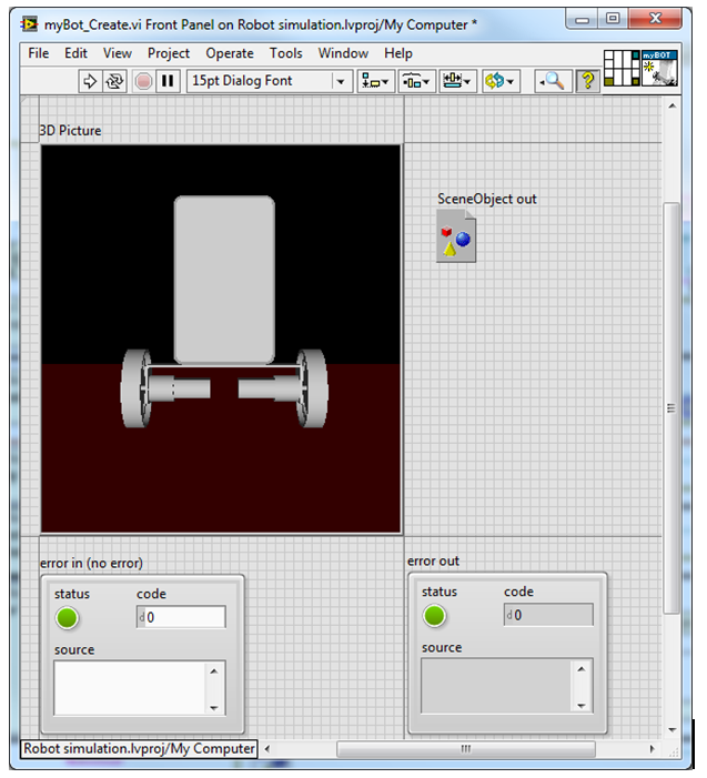
Fifth line explanation

Now we can see our 3D robot on the front panel by putting a 3D picture wired to the Scene Object Out indicator:
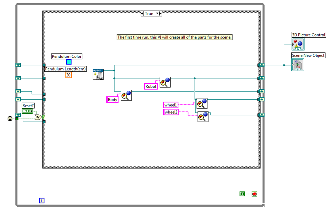
Software Implementation
We can test our 3D model with the linear invert pendulum labVIEW example. We implement our model in the subVI Draw_linear_Invert_Pendulum_sim.VI:
Then you can execute the main VI and see your 3D robot moving.
http://screencast.com/t/9i3Opkmxc
Conclusion
We created a simple behaviour simulation of the balancing robot by using an Invert pendulum on a trolley model. This model does not represent the real behaviour of our robot because we did not use the inertia energy of the Robot wheels and we did not take care of the friction of wheels.
