From Friday, April 19th (11:00 PM CDT) through Saturday, April 20th (2:00 PM CDT), 2024, ni.com will undergo system upgrades that may result in temporary service interruption.
We appreciate your patience as we improve our online experience.
From Friday, April 19th (11:00 PM CDT) through Saturday, April 20th (2:00 PM CDT), 2024, ni.com will undergo system upgrades that may result in temporary service interruption.
We appreciate your patience as we improve our online experience.
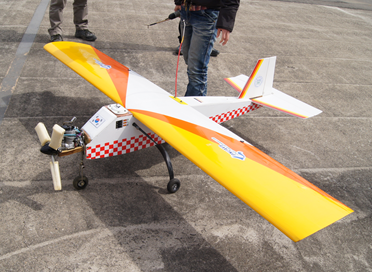
PNUAV7 UAV
Labview 2011, NI vision developemnt module 2011, NI PXI-1411 frame grabber
In this research, car classification algorithm is researched using aerial images. We choose three car types for this project (sedan, truck, bus) and programmed GCS to indicate order of priority. There are some technique must prepared for project. At first, UAV system can fly by itself using FCC(flight control computer). And UAV can do the searching flight and circling flight to find the target and obtain the target image. Stability and over 10-minute flight performance is also required. FCC of UAV should communicate with GCS during the flight and stable image stream from the UAV is also required. Finally car type classification can be done by real-time at the GCS system. There are summarized key requirements for this project.
1. Image can be obtained at the GCS in real-time.
2. Interlace effect from the vibration of the UAV should be eliminated.
3. User input device like Joystick, mouse and keyboard should be supported.
4. Construction of DB can be easily done.
5. Pattern matching algorithm robust for illumination changing is required
6. GCS can be easily programmed and integrity should be guaranteed.
1. Outline of this project
We conduct a project about car type classification using real-time image acquisition, transmission system and PNUAV7 UAV. Our main image processing algorithm is progressed like this figure.
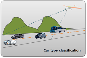 concept of our project

car type classification process
A camera equipped at the aircraft generally struggle for the elimination of interlace effect from engine and other vibration sources. Thus de-interlace treatment should be applied for the image. General and the easiest way of de-interlace is field extraction. By extracting only one odd or even field from the image, interlace effect can be eliminated. NI PXI-1411 have FPGA chip in the frame grabber and de-interlace treatment can be done without CPU. By this, de-interlace treatment can be done very fast and we can guarantee real-time performance.
To track the target, gimbal of equipped camera should be controlled by input command. We use the joystick and keyboard and function for these input devices can be easily programmed by library of LabVIEW2011.
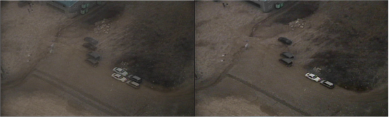
problem caused by interlace(left), de-interlaced image(right)
control buttons for camera gimbal
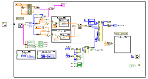
block diagram of camera gimbal control function
To assign a region of the target from the car image, command from the user is required. User watches screen and grab a target image by triggering joystick. Then assign a region of the target using mouse and this extracted image is used to classifying a car type.
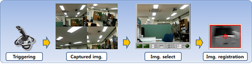
image matching process
To obtain a position and car type information of the target using the template image, we use pattern matching function included in NI vision development 2012. To conduct a pattern matching process, following processes are required and pattern matching results are shown.
preprocessing process before the target matching
2. Construction of database
For target image matching, various image of each car type should be required. Thus we utilize two methods.
The first method is image acquisition from the Google map. These days, Google map is offering the high quality 45 degree view of satellite picture, thus various images which have different pose and illumination condition can be acquired using this tool.
template image acquisition program using Google map
We make a clipboard image acquisition program using LabVIEW function and assign a car region using mouse and keyboard using this program. Selected car image region is resized by fixed size and is saved with continuously increasing filename. Using this program, various image of each car type can be easily acquired.
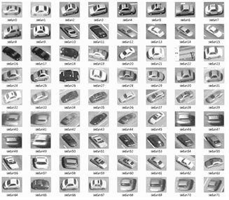
car template images obtained from Google Map
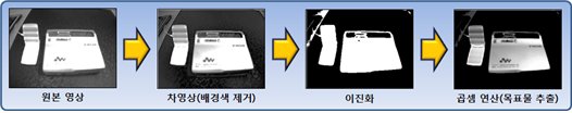
Second method for obtaining car template image is background subtraction. After obtaining car image from fixed camera with tripod, car template images are obtained autonomously by background subtraction method.
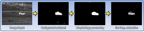
template image extraction process
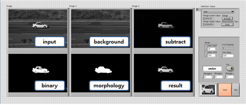
template maker VI using background subtraction
Using vision development module, this program can be easily make and utilize. At first, image from AVI file is loaded and then is subtracted from appointed background image. After subtraction, small noise is eliminated by morphological filter and then final template image is saved into fixed size image file.
3. UAV System configuration
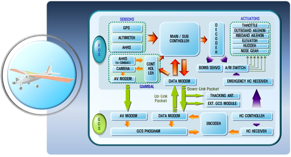
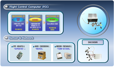
UAV system configuration
Our UAV system have two parts (FCS(flight control system), GCS(ground control system)). FCS has sensors like GPS, AHRS and FCC consisted with three PIC processors and some actuators. For the image acquisition, gimbaled camera developed by our lab is installed bottom of UAV. Acquired images are downlinked by RF video modem. Main processor of the FCC takes charge of UAV guidance and GCS data communication and sub processor takes charge of obtaining position and attitude of UAV from AHRS, GPS and controlling servo actuators. Detailed system configuration is in figure 2.
Hardware configuration of the PNUAV7
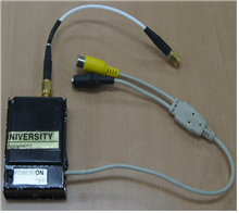
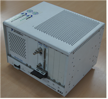
RF video trasmitter and NI PXI chassis equipped with PXI-1411 framgrabber
CS takes charge of data acquisition and transmitting command to the UAV. It also includes frame grabber, tracking antenna system and communication devices. We use the PXI-1411 frame grabber of NI and set up the frame grabber to print out images with odd frame only. Using this setup, we can easily applied de-interlace treatment and eliminate interlace effect cause by vibration of the camera.
4. Experimental results
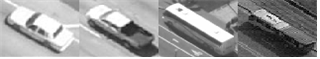
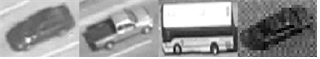
At first, we do the experiment using car images obtained from ground installed camera. Images of two sedans and one truck passing the way are used for the experiment. (We divided into three car type only, sedan, truck and bus.) Score of the matching is indicated from zero to one thousand. In this experiment, we can verify the matching possibility. Score of same car type is indicated highest score than other car type and it means that car type is classified correctly.
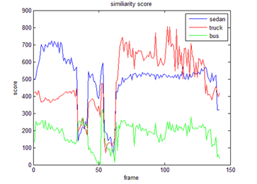
experiment movie car type classification result
After ground experiment, we verified performance using image obtained during the flight. In this experiment, we setup the program to print out the target which gets highest score for the sedan. NCC algorithm is not robust for the change of the target size, thus we applied four step pyramid image. (0.5X, 0.7X, 1X, 1.5X)
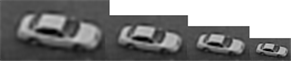
template pyramid image
car classification experimental result (sedan)
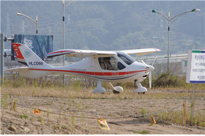
Light sports aircraft CTSW
In this experiment, the UAV is circling round above a white car in the ground and obtaining images of the car. The same templates of previous experiment are used.
Matching experiment using UAV
Using this vision GCS below, car type is classified using three car type during the flight. Each car type has 30~80 template images and resolution of the each image is 80*60. Matching time is recorded under 30ms for a frame.
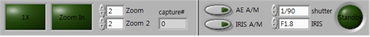
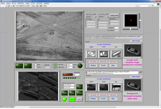 Front panel managing gimbaled camera and communication
We divede vision GCS into two window for convenience. In the first front panel, communication between FCC and GCS is managed and control command obtained from joystick for gimbaled camera is transmitted. Using trigger button of the joystick, captured image is delivered to second front panel and this image is used to car type classification. Similirarity scores are indicated on the front panel.
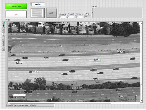
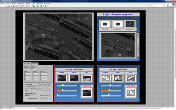 front panel for assigning a car region from the captured image
In the second front panel, captured images are arranged on the thumnail window and one image selected using keyboard by a user. After assigning a region of interest of the car, matching process is executed and them results are indicated on the front panel. Similarity score of each car type is calculated by two types of template images and indicated in the different indicator. Scores are sorted in ascending order. In thie experiment below, we can verify that score of sedan is higher than other car type.
398.493073, 360.248322, 599.117432
679.056519, 454.567932, 0.0000000
