- Document History
- Subscribe to RSS Feed
- Mark as New
- Mark as Read
- Bookmark
- Subscribe
- Printer Friendly Page
- Report to a Moderator
- Subscribe to RSS Feed
- Mark as New
- Mark as Read
- Bookmark
- Subscribe
- Printer Friendly Page
- Report to a Moderator
myRIO LED Matrix Interface with LabVIEW
By: Stephen Goadhouse
Overview of what project is:
For a collaborative project in graduate school, my team created a demonstration that made use of iRobot Create robots and 16 x 32 LED Matrices from Adafruit. I handled driving of the LED Matrix using the FPGA within the myRIO to handle the PWM. This was based on VHDL from Brian Nezvadovitz. The VHDL was modified to fix the ghosting issue that these LED Matrices can have if the PWM refreshes are not handled in a special way. There were also some VHDL modifications so that LabView can interface with the VHDL.
The attached zip archive contains a stand-alone myRIO project along with the VHDL code under rgbmatrix-fpga-master. There are some files under rgbmatrix-fpga-master from B. Nezvadovitz that are not used. Feel free to hook-up the LED Matrix as shown below and try out the RT Main.vi top-level.
Although our project made use of a iRobot Create, these files do not require a Create in order to use them, just a myRIO and a 16 x 32 LED Matrix. We powered the LED Matrix off of the Create's batteries so if a Create robot is not available, some other power source will be needed. The LED Matrix needs 5V and can sink nearly 3A when at full brightness although < 1A is typical depending on how bright the display is set.
The myRIO we used was the 1900 but perhaps it is possible to modify the project to target the 1950.
Wiring Up the LED Matrix to the myRIO:
The IDC connector on the LED Matrix almost matches what the myRio IDC connector needs although they are a different number of pins.
myRio - plan to use the right connector, B, put the pin-out is the same for A & B
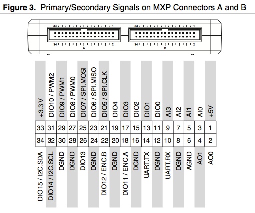
LED Matrix pin-out:

The myRio is a 34 pin connector and the LED Matrix has a 16 pin connector. So start with a 16 pin ribbon cable. Cut off one end. Get a 34 or 30 pin IDC connector and it will be installed on the free end of the 16-pin ribbon. To line up the signals and GND properly, before attaching the connector for the myRio, first seperate wire # 1 and #2 from the others. Space them out so that #1 goes to pin 11 (9), #2 goes to pin 13 (11), and then #3 - #16 goes to pins #15 - #28 (#13 - #26). So then the 34-pin or 30-pin connector gets plugged into the myRio and the 16-pin goes into the LED Matrix. The pin-out then becomes:
| LED Matrix Pin# | Signal | myRio Name | myRio 34-pin IDC |
| 1 | R1 | DIO0 | 11 |
| 2 | G1 | DIO1 | 13 |
| 3 | B1 | DIO2 | 15 |
| 4 | GND | DGND | 16 |
| 5 | R2 | DIO3 | 17 |
| 6 | G2 | DIO11 | 18 |
| 7 | B2 | DIO4 | 19 |
| 8 | GND | DGND | 20 |
| 9 | A | DIO5 | 21 |
| 10 | B | DIO12 | 22 |
| 11 | C | DIO6 | 23 |
| 12 | GND | DGND | 24 |
| 13 | CLK | DIO7 | 25 |
| 14 | LAT | DIO13 | 26 |
| 15 | OE | DIO8 | 27 |
| 16 | GND | DGND | 28 |
POWER For LED Matrix
To power the LED Matrix, connect to the iRobot Create cargo bay connector (or other power source).
| Pin # | Name of Cargo Bay Pin |
| 11 | Switched Vpwr (18.5VDC max) |
| 21 | GND (Battery GND) |
Since the robot power output is the battery voltage (16.5V - 18V) but we need 5V, then need something like this:
http://www.adafruit.com/products/1385?&main_page=product_info&products_id=1385
- Displaying all white with brightness = 100 and Factor = 1 (max power), using the UBEC set to 16.5V input
- Power Supply = 16.506V / 1.003 A / 16.558W
- At LED Matrix = 5.13V / 2.964A (measured with clip meter) = 15.2W
- 1.35W dissipated by the UBEC DC/DC supply - yes it gets very warm!
- However, with typical settings, expect to be 5W or less.

C or LV?: LabVIEW
Version of LV: 2013
Code: LEDMatrix_4_LATEST.zip attached
- Mark as Read
- Mark as New
- Bookmark
- Permalink
- Report to a Moderator
Hello
Can you send me instructions to display any image on the LED matrix ?
please email me at elbazzi@gmail.com
Thanks in advance 
Have a nice day
