- Document History
- Subscribe to RSS Feed
- Mark as New
- Mark as Read
- Bookmark
- Subscribe
- Printer Friendly Page
- Report to a Moderator
- Subscribe to RSS Feed
- Mark as New
- Mark as Read
- Bookmark
- Subscribe
- Printer Friendly Page
- Report to a Moderator
The Pitcher Perfect Tuner
Contact Information
University: The University of California, San Diego - Bioengineering
Team Members: Jason Caffrey, Eddie Gibb
Faculty Advisor: Dr. Gert Cauwenberghs
Email Address: jcaffrey@ucsd.edu
Project Information

Title: The Pitcher Perfect Tuner
Description
The goal of this project was to create an instrumental tuner for a trumpet that not only determined the pitch, but adjusted it for you. This concept was inspired by the difficulty of beginning trumpet players to learn tuning and recognize what pitch to listen to. Through automated adjustment, the system is insensitive to naturally out of tune notes and temperature variation. Using sound acquisition, signal processing, and mechanical control, a prototype was realized that found a pitch center within 3 seconds for a range of notes with an accuracy of 1Hz.
Products
To achieve low cost, high speed, and high resolution data acquisition, the NI myDAQ was purchased for this project.
NI Hardware: NI myDAQ
NI Software: LabVIEW 2010 student edition, NI ELVISmx
Other Hardware: Eastman TR-400 trumpet, Sony Vaio VGN-FW139E laptop, Arduino Duemilanove w/ATmega328 microcontroller with prototype boardshield, electret condenser microphone, powered prototype board, Power HD-2400A standard servo motor
The design project and all LabVIEW code is original and written for the sole purpose of the 2011 LabVIEW Student Design Competition.
Design Parameters
The desired product was a device that could be attached to a trumpet and adjust the pitch via mechanical manipulation of the main tuning slide. After speaking with local musicians, it was agreed that for a sustained pitch, a tolerance of ±5 cents is acceptable for solo performance. The cents scale is linear, with 100 cents between each note. However, the frequency change between notes is nonlinear. Over a large range of the practical scale for beginning trumpet players, a 5 cent error equated to an error of about 1Hz, making this the first design parameter.
Due to the need for fast resolution to the correct pitch, the second design parameter was that a settling time of 3s was required.
Lastly, due to the limitation of a self-funded prototype, a minimal cost was required.
Design Implementation
Device Design and Construction
To implement a prototype device, the Eastman TR400, a typical entry-level student trumpet, was used for this project. An attachment clamp was designed in Solidworks and constructed of ABS plastic via rapid prototyping, seen in figure 1 below.
(a) (b)
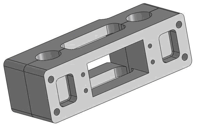
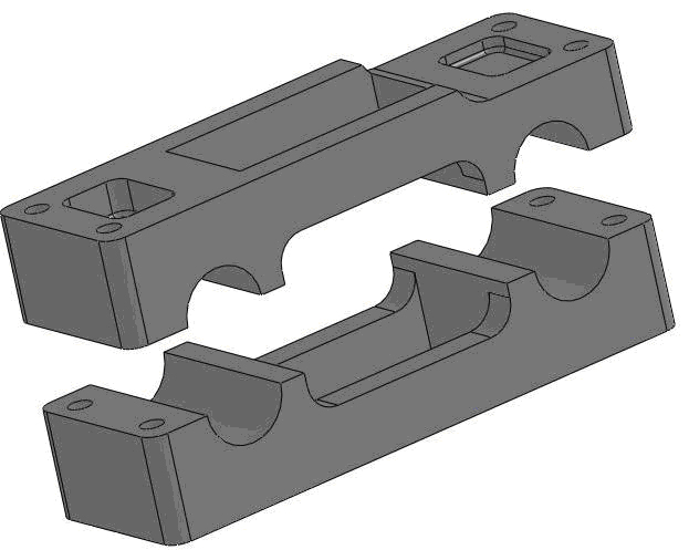
Figure 1. Solidworks 2009 model of attachment clamp in (a) closed view and (b) exploded view.
A Power HD-2400A standard servo motor was mounted in the attachment clamp, and the clamp was attached to the upper and bottom tubes of the trumpet’s tuning slide. Each component was secured using socket head screws and nuts.
Since the tuning slide moves linearly to adjust the pitch, an offset crank slider linkage was constructed to translate the rotational motion of the servo motor into linear motion. A modified Dubro #4-40 E/Z Adjust Ball Link was attached to the servo arm and connected to a modified Dubro Kwik-Link via #2-56 threaded rod and cyanoacrylate glue. The receiver on the tuning slide was a modified ¼” cable clamp connected to the post of the tuning slide with rubber added to prevent slippage. A triangular piece of polycarbonate sheeting was glued to the cable clamp and custom drilled to fit the pin of the kwik-link to allow for rotation at the pin joint of the kwik-link and the ball joint. Rubber was added to the clamp to prevent slipping on the tubes. The attachment clamp with servo motor and linkage attached can be seen in figure 2. A diagram of the slide motion can be seen in figure 3. The slide was kept lubricated using Zaja trumpet slide lube.
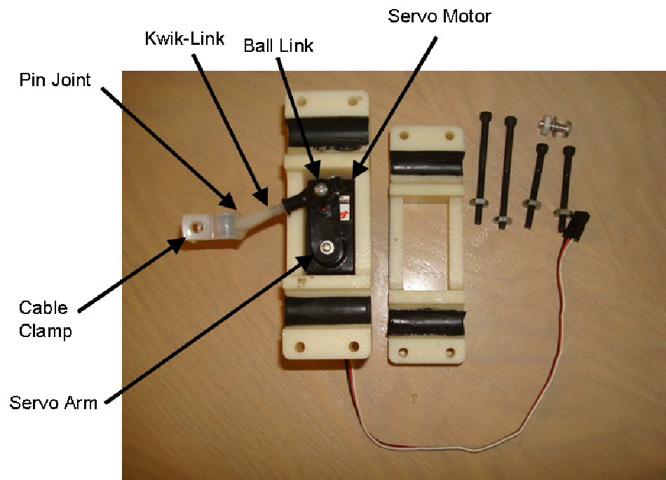
Figure 2. Picture of attachment clamp with servo motor and offset crank-slider linkage in exploded view. Linkage parts are labeled. Note: attachment clamp side on left appears larger due to higher elevation from servo motor body.
(a) (b)
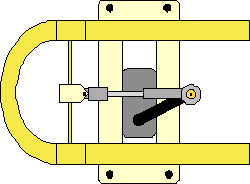
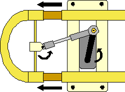
Figure 3. (a) Shows diagram of tuning slide in fully retracted position. (b) Shows diagram of tuning slide in extended position. Arrows indicate direction of motion.
Signal Acquisition
To acquire the pitch of the sound being played on the trumpet, a microphone circuit was made using an EM9465P electret condenser microphone and a simple preamplifier. The circuit diagram can be seen below in figure 4.
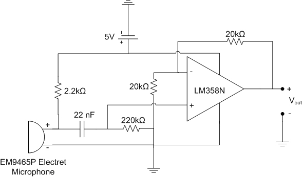
Figure 4. Circuit diagram of microphone with preamplifier. Vout was read by the differential analog inputs of myDAQ. Diagram made in Microsoft Visio 2007.
The circuit was powered from the +5V power from the NI myDAQ and built on the prototype board of the Arduino duemilanove prototype shield. Data was acquired using the differential analog inputs of the myDAQ via LabVIEW on a laptop computer. A picture of the setup is shown in figure 5.
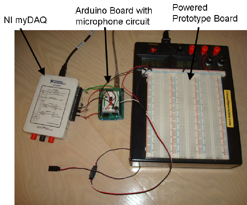
Figure 5. Picture of data acquisition hardware labeled. Cable end shown on bottom left is connected to the servo motor.
Since expected frequency values ranged from 200-1000Hz, a sampling rate of 4096 S/s was chosen prevent aliasing by the Nyquist Criterion, and maintain good signal representation.
Signal Processing
The balance in signal processing between speed and frequency resolution posed the largest problem for this project, and traditional methods of frequency analysis were replaced by novel techniques.
To determine the peak fundamental frequency of the input sound wave, the efficient Fast Fourier Transform (FFT) was first explored. However, for a desired resolution of 0.1Hz, this required that 40960 samples be taken, equating to 10 seconds of data at 4096Hz by the FFT equation below.

Where Δf is frequency resolution, fs is sampling frequency, and N is the number of samples. This was an obvious problem, as each iteration of motion would take over 10s, with pitch settling times requiring multiple iterations.
A new approach was taken, which exploited the fact that a high resolution frequency analysis was desired at only the fundamental frequency peak, rather than across the entire frequency spectrum. This approach utilized a looped 10th order Butterworth filter to determine the signal amplitudes of large frequency intervals (20 Hz) across the expected range of frequencies (200-1000Hz).

Figure 6. Screenshot of LabVIEW block diagram for first filter. SubVI can be found in attached file “Filter_1.vi”.
The trumpet, like most other instruments, produces not only a fundamental frequency, but also a number of harmonics, as seen below in figures 7 and 8.

Figure 7. Actual recording of 8ms of trumpet of concert pitch F (349.23Hz). Recorded using Adobe Audition 1.5.
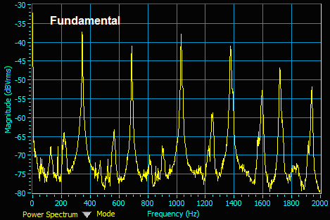
Figure 8. Frequency analysis using NI ELVISmx Dynamic Signal Analysis of concert pitch F (349.23Hz). 10 Averages with 800 line resolution used. The fundamental frequency peak is labeled.
The amplitude of these harmonics depends on the fundamental pitch, as well as the instrument’s natural resonances. This often leads to harmonics having the highest peak magnitude. To account for this possibility, the frequency amplitudes were normalized by dividing by frequency, to favor the lower frequency fundamental peak.
After selecting a range of 20Hz, which contains the fundamental frequency, a ±20Hz region was selected around this range (60Hz range total) and passed through a second 10th order Butterworth filter with a small frequency interval of 2Hz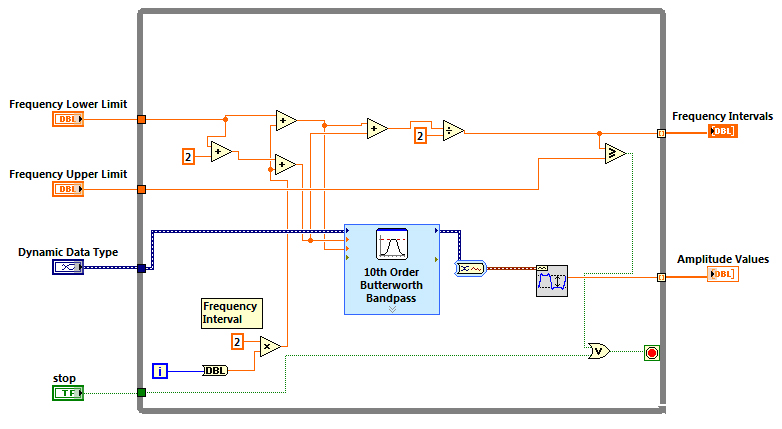
Figure 9. Screenshot of LabVIEW block diagram for second filter. SubVI can be found in attached file “Filter_2.vi”.
A ±20Hz interval around the 2Hz interval with the highest amplitude from the second filter was then selected and fitted to a second order low pass filter equation, as seen below.

Where A is the amplitude, a is the normalized DC gain, x is the frequency, f is the peak frequency (highest amplitude), and d is a scaling factor. From the optimization of parameters a, d, and f, the peak frequency was of interest. For a sustained generated single frequency sine wave, the fitted frequency was within 0.1Hz.
The values of the filter intervals (20Hz, 2Hz) and curve fitting was selected for minimized iteration time, with sufficient frequency accuracy. With a single filter at a resolution of 2Hz, 400 loop iterations would be necessary, whereas the double loop method requires 20 iterations for the 20Hz filter and 40 iterations for the 2Hz filter, needing only 60 iterations overall.
Motion Controller
With an accurate measurement of the fundamental frequency of a given note, this frequency is compared to an array of known note values with corresponding frequencies, based on the American standard tuning of 440Hz for the A4 note. The user has the option to set the A4 frequency, which offsets each note value, to allow for international users. The difference between the known and actual frequencies represents the frequency error.
From repeated sustained pitches played, the frequency was measured at different tuning slide extension lengths. It was observed that the relationship for a given note was linear, with high correlation. As the tuning slide was pulled out, the pitch lowered, as expected.
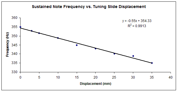
Figure 10. Plot of fundamental note frequency for different displacements of the trumpet tuning slide for a sustained F4 (349.23Hz). Black line indicates linear regression. Plot and linear regression performed using Microsoft Word 2003.
By dividing the frequency by this slope, a proportional slide displacement error was initially determined. However, it was seen that the system was prone to large overshoot and settling times, as well as oscillations. To correct this, a simple PID control algorithm was written and the parameters were manually tuned (P = 0.6, I = 0.005, D = 0.3) for short rise time, minimal overshoot, and stability.
This displacement error was then scaled to suit the 0-10V input voltage range of the Arduino microcontroller, and an analog voltage signal was outputted from the myDAQ to the Arduino board. The use of a separate microcontroller was necessary to control the servo motor directly due to the capacity to output a Pulse-Width Modulation (PWM) signal to the motor, which the low-cost NI myDAQ did not have. Also, programming the Arduino (similar to C++) for setting servo motor arm angles allowed use of available servo libraries.
After backcalculating displacement error using the Arduino, a relationship between tuning slide displacement and servo arm angle was necessary. From the nature of the mechanical linkage, the displacement is a complex sinusoidal function of angle, with a 360º period. Since the displacement change decreases as the servo arm approaches 0º or 180º (at which the slope becomes negative), a range of 30º to 150º was set, which allowed for a sufficient displacement range.
Using these boundaries, the tuning slide displacement was measured for different servo arm angles, as controlled by the Arduino board. Through only a portion of the sinusoidal relationship, a simpler cubic function could be fitted with high correlation.
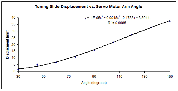
Figure 11. Plot of slide displacement measured using calipers for a range of servo motor angles set using Arduino microcontroller. Black line indicates cubic regression. Plot and linear regression performed using Microsoft Word 2003.
By reading in the current servo angle, the tangent slope is determined using the derivative of the fitted equation. By dividing displacement error by this slope, the angle error is determined. This angle error is then added to the current angle and the new angle is set using the Arduino board.
Overall the code loops with an average time of 380ms while the tuner is adjusting pitch with a final resolution range of 2Hz after 3 seconds. A flow diagram of the overall process can be seen below, as well as a picture of each component connected.
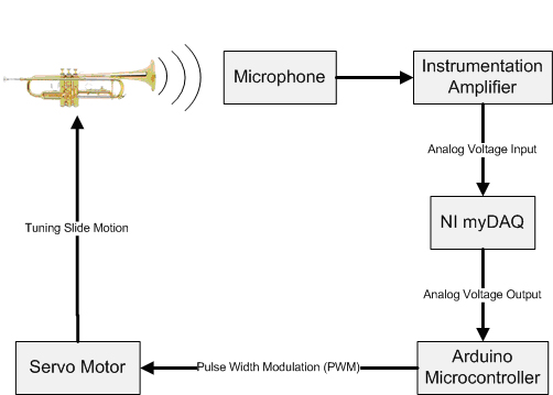
Figure 12. Flow diagram of the Pitcher Perfect Tuner system. Labeled arrows indicate data flow while boxes/trumpet indicate hardware components.
Figure 13. Picture of overall setup with all components connected.
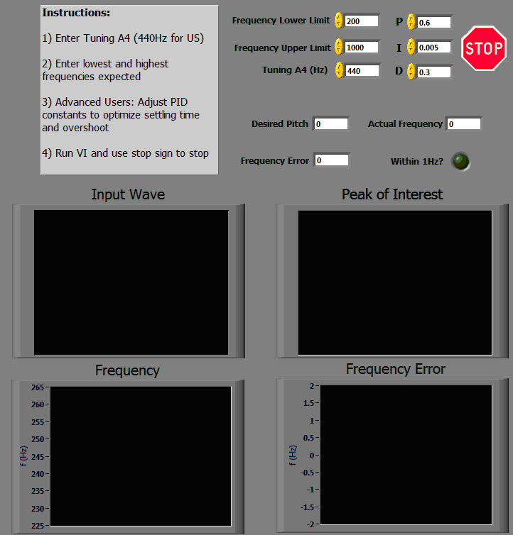
Figure 14. Screenshot of LabVIEW “Tuner.vi” Front Panel. Note: VI is not running.
LabVIEW
The use of the LabVIEW programming environment allows for high speed acquisition, as well as powerful filtering and curve fitting functions, which is essential for real-time controls. The ability to have high resolution and speed inputs and outputs using the myDAQ, while having a low cost, was essential for our project. The use of powerful analysis tools such as ELVISmx made for fast and easy signal analysis.
Project Cost
The cost of materials for the prototype, excluding the NI myDAQ, laptop, and powered prototype board, was under $100.
Project Video
Acknowledgements
We would like to thank Dr. Gert Cauwenberghs, Dr. John Caffrey for his assistance during the attachment clamp construction, and Eileen Hsu for all her help and support. We would especially like to thank Anaheim Band Instruments for use of the trumpet.
Attachments
Attached are the LabVIEW project with VIs, as well as the Arduino code (TPT.pde). The .zip file contains all files.
Biographies
Jason Caffrey is a 3rd year undergraduate Bioengineering student at the University of California, San Diego. Jason has extensive experience with LabVIEW in data acquisition and controls for mechanical testing devices. Jason is a Certified LabVIEW Associate Developer (CLAD) and is currently pursuing Certified LabVIEW Developer (CLD) certification.
Eddie Gibb is a 3rd year undergraduate Bioengineering student at the University of California, San Diego. Eddie has significant class and project experience with LabVIEW and graphic design.
- Mark as Read
- Mark as New
- Bookmark
- Permalink
- Report to a Moderator
Hi Jpctrumpet
Thank you so much for your project submission into the NI LabVIEW Student Design Competition. It's great to see your enthusiasm for NI LabVIEW! Make sure you share your project URL(https://decibel.ni.com/content/docs/DOC-16427) with your peers and faculty so you can collect votes for your project and win. Collecting the most "likes" gives you the opportunity to win cash prizes for your project submission. If you or your friends have any questions about how to go about "voting" for your project, tell them to read this brief document (https://decibel.ni.com/content/docs/DOC-16409).
I'm curious to know, what's your favorite part about using LabVIEW and how did you hear about the competition? Nice work with the NI myDAQ!
Good Luck, Liz in Austin, TX.
- Mark as Read
- Mark as New
- Bookmark
- Permalink
- Report to a Moderator
Hi Liz,
I've been using LabVIEW in a campus research lab for ~1.5 years to control mechanical testing devices and collect transducer data. I heard about the competition from exploring the NI website and getting emails from NI. What I like most about LabVIEW is the ease of device control and high speed data acquisition. With a vast array of VIs to use, application development goes quickly with great results.
Thanks Liz!
- Jason
- Mark as Read
- Mark as New
- Bookmark
- Permalink
- Report to a Moderator
Great job, guys! This is a cool project, and your case study and video demonstration are both very good.
- Mark as Read
- Mark as New
- Bookmark
- Permalink
- Report to a Moderator
Thanks, Jack!
- Mark as Read
- Mark as New
- Bookmark
- Permalink
- Report to a Moderator
As a music player, I definitely understand the importance of having in tune instruments! This is a great idea!
- Mark as Read
- Mark as New
- Bookmark
- Permalink
- Report to a Moderator
Great project, gentleman! I've played a little brass in my past and can see how important a device like this could be especially for those just learning how to play. Best of luck.
- Mark as Read
- Mark as New
- Bookmark
- Permalink
- Report to a Moderator
Keep up the great work, guys! This is by far the most innovative invention for a musical instrument I've ever seen. Having the ability to play a pitch and hear it corrected would provide valuable ear-training for beginning musicians of any age. I was shocked to see the extremely fast response time by the LabVIEW program to correct the pitch.
This concept could be applied to a vast number of other instruments!
- Mark as Read
- Mark as New
- Bookmark
- Permalink
- Report to a Moderator
Greetings from Austin, Texas Jason Caffrey and Eddie Gibb,
National Instruments is thrilled to invite you all to NIWeek, August 1-4 2011, in Austin, Texas. Our panel of judges thought your project submission was innovative, fun, and an excellent display of NI technology.
Therefore, we hope that you are available to attend NIWeek. Your flight, hotel, and conference passes for this event will be free of charge should you accept our invitation.
Please respond to this email as soon as possible so we can move forward reserving your flight, hotel, and conference passes through our travel group.
Thank you and congratulations!! This is a wonderful opportunity and we are looking forward to meeting you.
Also -- what year are you in school?
Best,
Liz Savage and Mark Walters.
- Mark as Read
- Mark as New
- Bookmark
- Permalink
- Report to a Moderator
Good job!! This is an innovative use of rapid prototyping in music.
- Mark as Read
- Mark as New
- Bookmark
- Permalink
- Report to a Moderator
Great job! how did you guys come to this idea or pick this project?
Good luck,
Hema
- Mark as Read
- Mark as New
- Bookmark
- Permalink
- Report to a Moderator
Excellent design. Keep it up. We expect more innovative ideas in near future.
Wish you all the best.
