- Document History
- Subscribe to RSS Feed
- Mark as New
- Mark as Read
- Bookmark
- Subscribe
- Printer Friendly Page
- Report to a Moderator
- Subscribe to RSS Feed
- Mark as New
- Mark as Read
- Bookmark
- Subscribe
- Printer Friendly Page
- Report to a Moderator
SquidROV: A Biomimetic ROV Propulsion Prototype / University of Edinburgh
Contact Information
University: University of Edinburgh
Team Members (with year of graduation): Espen Johan Magnussen (MEng, 2014)
Project Supervisor: Dr. Aristides Kiprakis
Email Address: espen.johan.magnussen@lyse.net
Project Information
Title: SquidROV
Description: The purpose of the project is to develop a biomimetic submarine propulsion system and attach it to a hull to create a remotely operated vehicle. Such a propulsion system is more energy efficient and generates much less turbulence than a propeller-based system of equivalent thrust. Our prototype propulsion system is controlled and operated wirelessly using a MyRIO. This project was developed by me for my final year MEng individual project, and has taken the equivalent of two months full time work spread over one academic year. The project has run in parallel with a larger research project at the Technological Educational Institute of Crete, Greece and good interaction has occurred throughout the project.
Products:
Hardware:
- MyRIO 1900
- 7.4 V, 4250 mAh LiPo battery
- 10 Digital servo motors
- L3G4200D three-axis gyroscope
Software:
- LabVIEW 2013 - SP1
- MyRIO toolkit
- System and control toolkit
- FPGA toolkit
- Xilinx Tools
- SolidWorks (for the design of the hull and the 3D printed fin parts)
The Challenge:
The goal of the SquidROV project was to develop a biomimetic submarine propulsion system based on an undulating fin system, similar to that of the manta ray, cuttlefish or squid. The undulating fin would then generate a travelling wave along the length of the fin, producing thrust and manoeuvrability for the vehicle. In order to achieve this, the wave form of the travelling wave needed to be generated, as well as controlled during normal operation. A particular challenge was changing the operational parameters of the propulsion system during operation while maintaining a smooth and natural wave form.
The Solution:
Mechanical design:
The design of the mechanical parts that make up the SquidROV is a major part of the project. The high-level design goal set forth at the beginning of the project was to create a system consisting of ten servo motors mounted on a rigid surface with a flexible membrane mounted between them. From this, the design of the SquidROV was developed. The resulting vehicle can be seen in Figures 1 and 2.
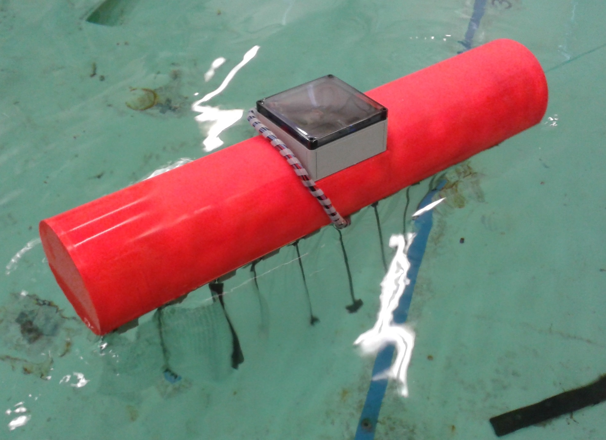
Fig. 1: First trial of the SquidROV in water.
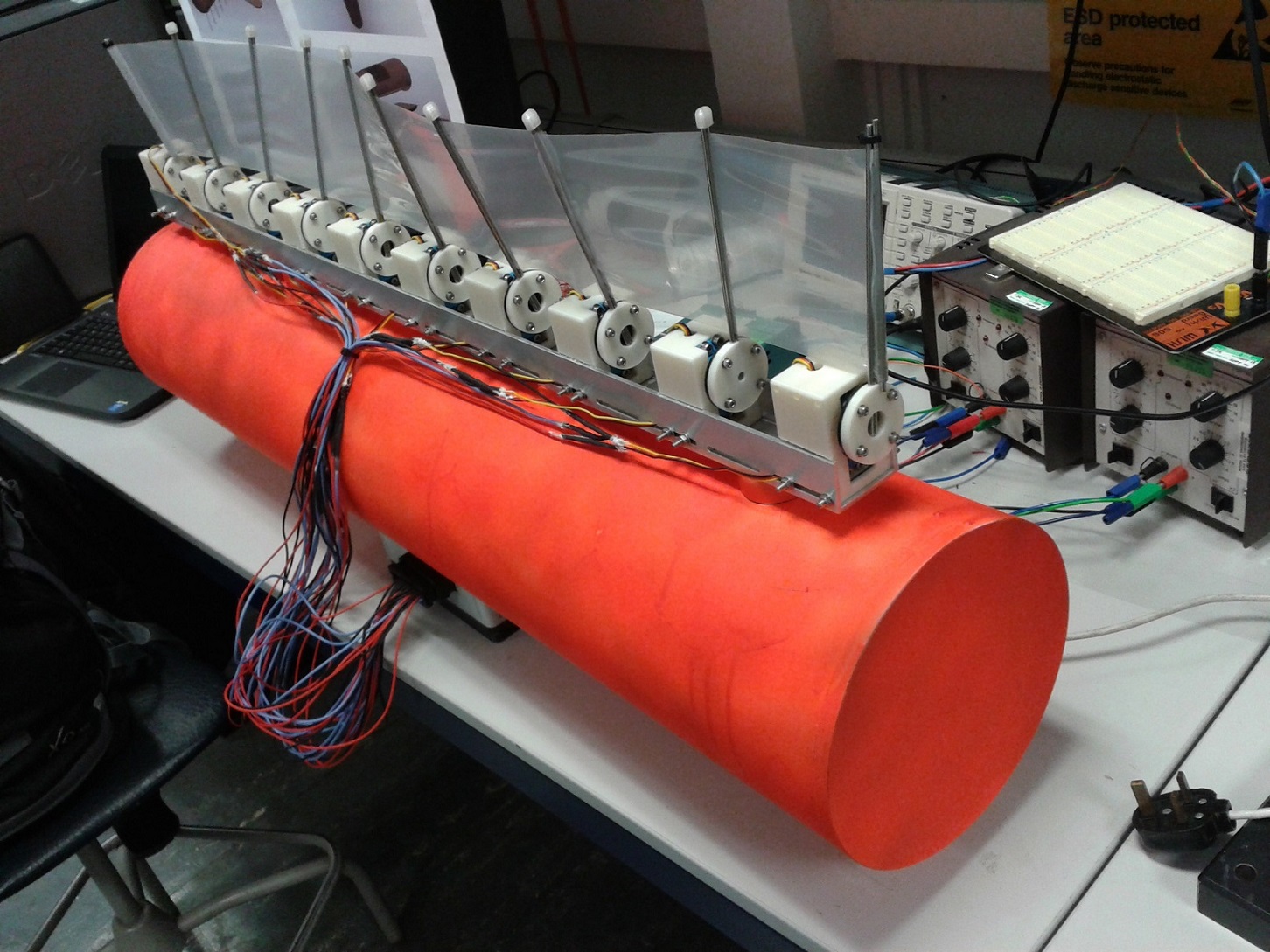
Fig. 2: SquidROV under development in the lab, upside down.
The SquidROV consists of two main mechanical components; the hull and the spine.
The hull
The purpose of the hull is first and foremost to keep the SquidROV from sinking. The final version of the SquidROV will be completely submersible, but at this stage it is floating on top of the water. The other function of the hull is to house the electronics used to power and control the fin. For more information, see control systems below. Lodged in a compartment in the middle of the hull is a LiPo battery, the MyRIO and a small PCB for connections. Another version of the hull was designed to include a set of stabilizing wings and internal electronics compartment as well, but was not manufactured due to limited time and resources. An illustration of the alternative design can be seen below on fig 3, whereas the design manufactured can be seen in fig. 1 and 2. The purpose of the stabilizing wings was to prevent the SquidROV from swaying from side to side as the undulating fin oscillates, potentially improving the overall thrust generated.
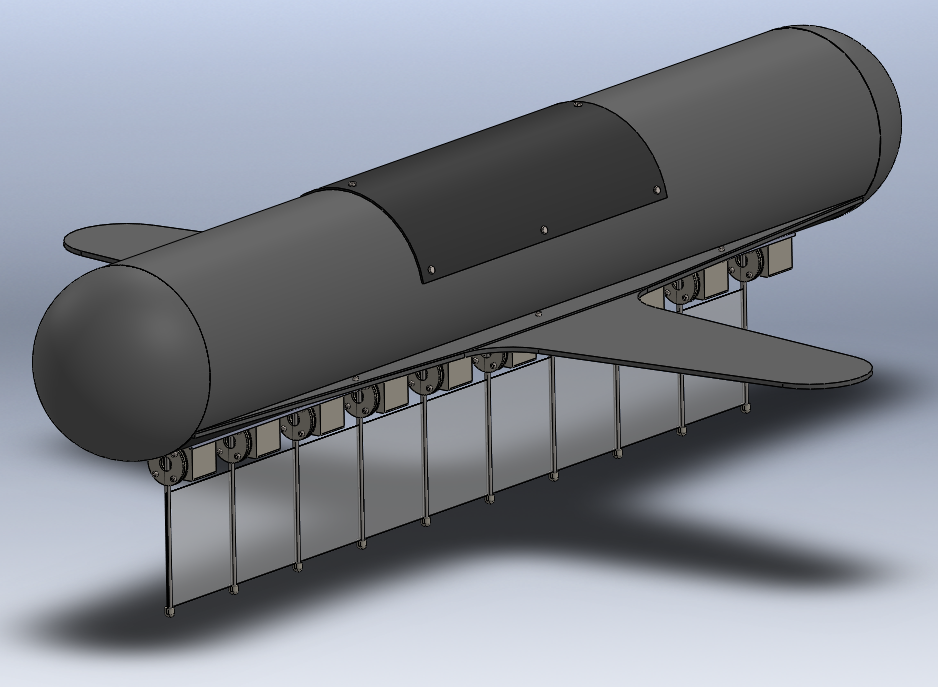
Fig. 3: Alternative hull design with stabilizer fins and internal electronics compartment.
The spine
The spine assembly makes up the undulating propulsion system in the SquidROV, excluding the control electronics. It consists of ten servo motors mounted to a rigid central spine. The servo motors are a vital part of the propulsion system. For the SquidROV project the HS-5646WP servo from HiTec is used. It was chosen because it is rated IP67 (waterproof), is controlled digitally using a PWM signal, has high torque ratings and is reasonably priced. On each servo motor there is a set of stainless steel rays mounted to the arm of the servo, which can move in an arc of approximately +/- 40 degrees. Between each set of rays a thin silicone membrane is wedged and secured. This silicone membrane runs the length of the spine, forming one continuous flexible fin. When a travelling wave is generated along the spine by altering the angle of the various servos, the membrane will move and stretch, pushing the surrounding water in one direction and propelling the SquidROV in the other. A picture of the assembled fin can be seen in fig. 4, and a demonstration of the travelling wave can be seen in video 1 further down. Note that the fin is lying upside down in the picture, as the picture was taken in the laboratory.
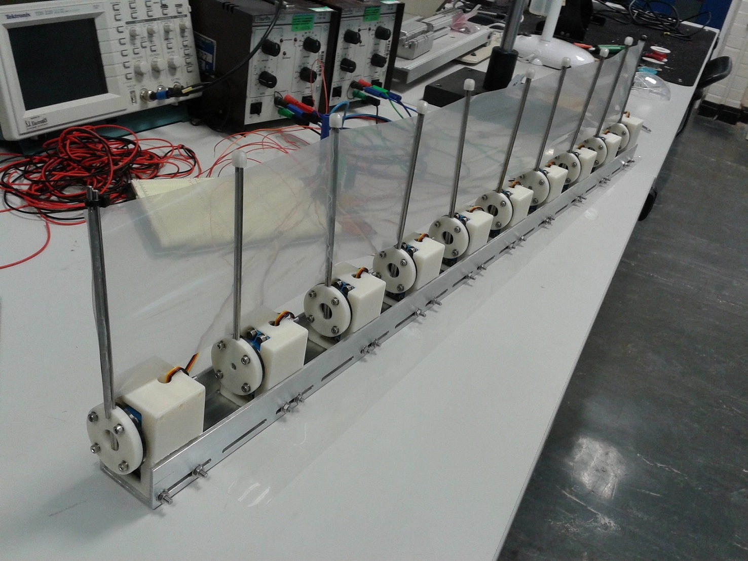
Fig. 4: Spine assembly with ten servo motors and flexible membrane, upside down.
Central Pattern Generator
In order to optimise the wave form of the undulating fin propulsion system, an artificial Central Pattern Generator was implemented. A central pattern generator is most commonly refereed to when talking about a neural network capable of producing rhythmic outputs without the need for regular sensory feedback. Breathing is an example of movement that is controlled by a CPG in humans. In this project, an artificial CPG was used to create a smooth and natural swimming pattern. You may ask: "But the fin is only producing a sine wave. Surely it could be done in an easier way?" And you would be technically correct; when the fin is swimming in steady state operation, all the CPG would do is produce a sine wave with a phase bias between each servo. But the steady state operation is not where the interesting effects of the CPG is found. The reason a CPG is superior to, for example, a simple sinusoidal wave form generator is that the CPG handles changes in the operational parameters far better than a simple wave form generator. If utilizing a simple wave form generator, changes in the operational parameters like frequency and amplitude cause uncoordinated and sudden changes in the motion of each servo motor. These discontinuous transitions between wave forms would interrupt the water flow around the fin, thus reducing efficiency, and also potentially resulting in increased stress on the servos causing fatigue or potentially critical damage. By creating an artificial CPG, it can be ensured that the transition between wave forms is smooth, regardless of what operational parameters are changed.
The CPG scheme used in the SquidROV is described by three equations:
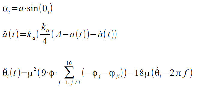
Where:
- α: angular displacement of ray.
- a: current amplitude of wave.
- θ: current phase of ray.
- ka: damping factor for amplitude.
- A: desired amplitude.
- i: ray number.
- φ: phase bias.
- μ: damping factor for phase bias.
- f: desired frequency.
These equations are implemented by the MyRIO using the simulation and control toolkit, and the code is explained in greater details below. A demonstration of the artificial CPG running on the MyRIO is presented in video 1. Note particularly the point around 0:32, where the operational parameters is abruptly changed from having one wave along the spine to haveing two full waves. Note the smooth transition between the two states, and how it is very difficult to tell exactly when the transition happens. This is an excellent example of the benefit of an artificial CPG.
Video 1: Dry test of biomimetic propulsion system using an artificial central pattern generator.
Control system
In addition to the various parts needed for the mechanical manufacture of the SquidROV, a second set of parts is required for the control system. The control system consists of the physical components required to create the control system for the SquidROV and the software developed. The overall schematic of the control system components can be seen on fig. 5. This figure shows the overall connections between the MyRIO, the servo motors, the battery and the gyroscope. (Note: The gyroscope is not utilized at this stage, but was included in the design to provide a platform for further development. See future developments for details.) A photo of all the components assembled within the box is shown in fig. 6.

Fig. 5: SquidROV overall connection scheme.
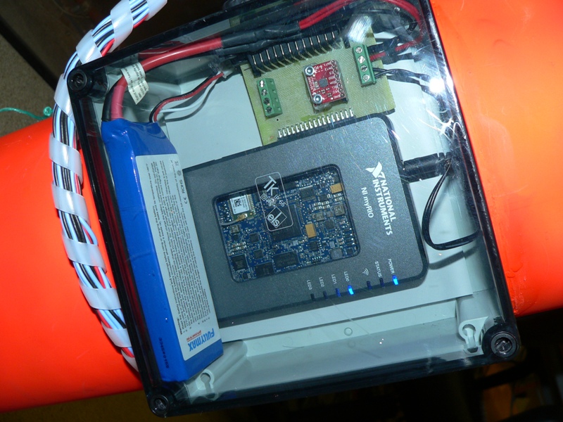
Fig. 6: SquidROV electronics assembly inside the IP67 box.
The brain of the SquidROV is the MyRIO. It is perfect for the SquidROV project as it has very high processing power as well as the required PWM capabilities to control the digital servo motors. This enables it to run a CPG-scheme and control all the servo motors that make up the propulsion system. In addition to this, the MyRIO has an embedded wireless module, enabling it to communicate with a computer wirelessly real-time. This let the SquidROV become completely autonomous, having all the components required for operation on-board. The SquidROV can operate independently, and the only information communicated with the on-shore computer is the commands specifying the high-level operation and the current status of the SquidROV. If no new commands are given, it will continue operating using the previous set of commands for as long as it has power, or it receives new commands. More details will be covered in the software section. The MyRIO also has a built-in three-axis accelerometer, which in conjunction with the three-axis gyroscope provides the basis for an inertial guidance system (see future developments for details).
As the SquidROV is designed to be autonomous, an on-board power source is required. The battery chosen for the power source is a 2-cell lithium-polymer battery, 7.4 V with 4250 mAh capacity. The battery is very small and light weight compared to other batteries with the same capacity, but is still capable of powering all the servo motors and the MyRIO at once for 20-40 minutes.
Software
The following section will cover the software developed for the SquidROV project. It will detail the overall code run in the main program, as well as focus on the major building blocks of the code, i.e. the FPGA code, and the generator blocks used in the central pattern generator. The full set of program files can be found in the attached Software folder.
FPGA code
The FPGA code is different from the real-time code in that it runs continuously on the hardware. Some parts of the code were developed for the project, and some parts were copied from the default FPGA code supplied with the MyRIO. In order to generate PWM signals to control the servo motors, some coding was required as it was desirable to output the PWM on a custom pin map. The PWM generation is done by having a loop keeping track of the number of milliseconds passing, and comparing this to the desired high time value. The overall time for one period is 0.02 seconds, so the PWM generation loop sets the output high for the specified duration, then low for as long as it takes to get to 0.02 seconds period, and then the cycle is repeated. The ability to use the on-board accelerometer, ADCs and SPI bus has been copied from the default program, and enables the use of higher level functions found in LabVIEW. See fig. 7 for a section of the FPGA code.
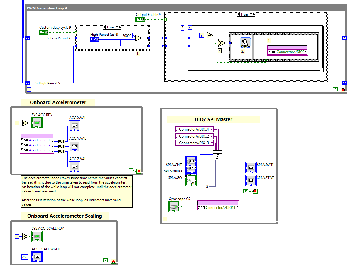
Fig. 7: Section of FPGA code.
Main program
The main program running on the MyRIO while the SquidROV is operational has several stages. First, the MyRIO receives input from the operators via the wireless network. The operator runs a VI on LabVIEW on a nearby computer, and the MyRIO communicates with this to receive inputs. If none is given, it will operate using standard values. The inputs are mainly instructions of what frequency, amplitude and phase bias to operate at, and some constant controls like damping factors and simulation time. It is also possible to enter the settings in the form of wave speed or number of complete waves present on the fin, depending on the preference of the operators. The second stage is then to convert all the inputs into useful values, i.e. convert desired wave speed to operating frequency etc. The program then enters a simulation and control loop. This loop is specifically designed to handle simulation and controls, and is ideal to implement the CPG. Inside this loop, the current angle and angular velocity of each of the ten servos as well as the current amplitude and current change in amplitude is combined to simulate the CPG. The duration of the simulation is determined by the total runtime of the main program loop. The total loop time is calculated at the end of each loop cycle, and the simulation setting is set so that it simulates the state at the end of the main loop. The output of the simulation loop is then converted into microseconds and sent to the FPGA PWM loops to serve as input, thus controlling the current angle of the physical servo motors. The full code can be found in the attached compressed folder Software. Fig. 8 shows the GUI created to communicate with the MyRIO.
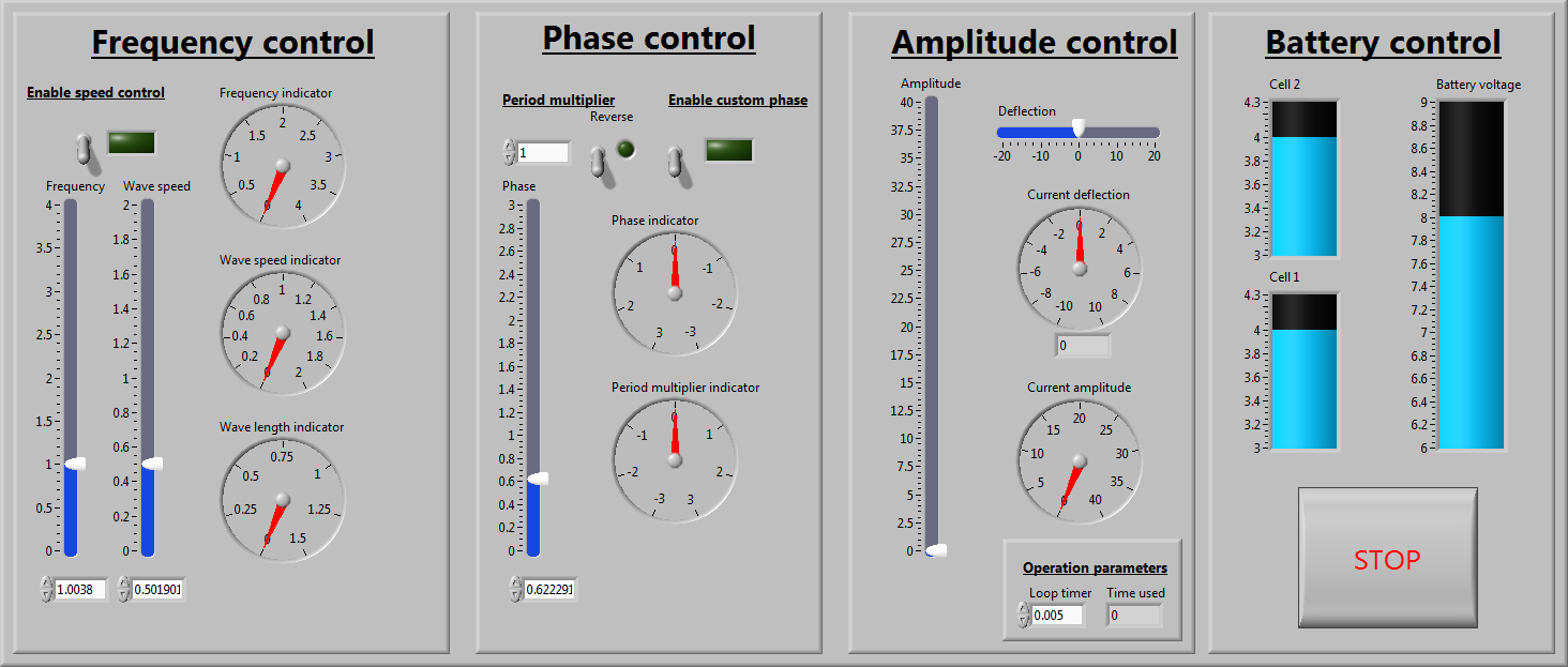
Fig. 8: GUI developed to monitor and control the SquidROV wirelessly.
Angle generator
The angle generator is a sub-block designed for the simulation and control loop. This sub-block generates the desired angular deflection of a particular servo, based on the input parameters given to the function. It implements the 3rd equation mentioned in the CPG section. It takes the desired frequency and phase bias as inputs, as well as the current angle of all the other servos, the damping factor and the previous angle and angular velocity of the current servo. It outputs both the angle and angular frequency, which loops around to the input in the main program. The overall code contains ten of these sub-blocks, one for each servo motor. The code block can be seen in fig. 9.
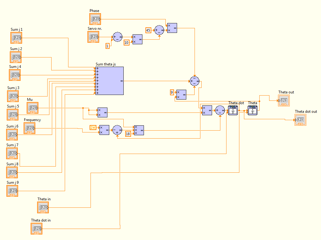
Fig. 9: Angle generator code block.
Amplitude generator
The amplitude generator is very similar to the angle generator, but it is a significantly simpler system. It implements the 2nd equation mentioned in the CPG section. Only one block of the amplitude generator is used in the main program, as it creates universal amplitude for all the servos. It accepts the desired amplitude as input, as well as the damping factor and the previous values for amplitude and change in amplitude. The output of for the block is the amplitude and the current change in amplitude. Details can be found on fig. 10.
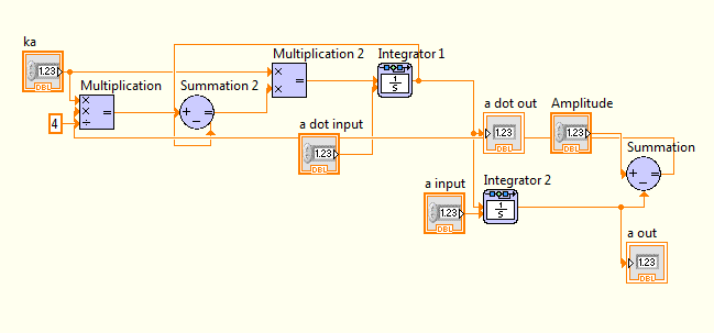
Fig. 10: Amplitude generator code block.
Result
The result of the SquidROV project can best be demonstrated by showing the final result in action. Video 1 from above shows as mentioned a dry test of the biomimetic propulsion system and CPG scheme. Video 2 shows the assembled SquidROV swimming around in various wave tanks and flumes at the University of Edinburgh. Several different materials and configurations of fins was tested, with variable success.
Video 2: SquidROV wave tank tests.
Overall, the SquidROV project has been very successful, and some of the success can be directly attributed to the MyRIO and LabVIEW system. Early designs of the control system considered the use of an Arduino MEGA or a Raspberry PI for simple sine wave generation. By using the MyRIO instead, we were able to not only control the servo motors to form a sine wave, but also add the CPG and wireless control. The ease of which we have been able to implement advanced computing functions have enabled us to focus on advanced operation and control of the SquidROV, rather than spending a lot of time on the lower-level programming and implementations.
Level of completion: Fully functional with platforms for future development integrated. This section of the SquidROV project is considered to be completely finished. Research and development will however continue, and future revisions of the SquidROV project will likely be seen, utilizing an inertial guidance system and a dual-fin propulsion system.
Time to build: This project has been ongoing from late September 2013 to early April 2014. It was developed alongside my studies and has required the equivalent of two months full time work (1/3 of my total study workload), spread over the course of the academic year. These two months included all the preliminary work, CAD design and manufacturing of the mechanical parts, LabVIEW programming of the myRIO, design and development of the electronics, system assembly and testing, and finally writing of the project report.
Additional revisions:
Even though this phase of the SquidROV project is completed, development will carry on. The research and development of the SquidROV will continue in the form of a summer internship during the summer of 2014, and then as a couple of new MEng projects during the next academic year. The first MEng project will involve the design and manufacture of a fully submersible prototype ROV with two horizontal fins for increased manoeuvrability and speed, also utilising inertial guidance systems such as the internal 3-axis accellerometer and an external gyroscope. The second MEng project will look into alternative methods for underwater communication with the myRIO based SquidROV, including ultrasound and visible light data transmission. A further idea for a project is to create an intelligent fin controller based on artificial neural networks and/or genetic algorithms that will actually be able to learn how to swim, rather than using the pre-defined central pattern generator. Implementation of all these ideas would not be so readily possible if we didn't use a platform so versatile and easy to learn as the myRIO/LabVIEW.
Additional resources
For anyone interested in learning more about the SquidROV project, some additional recourses has been provided for convenience:
- Project report: Development of Biomimetic Submarine Propulsion System, attached as pdf.
- Project web page: https://www.wiki.ed.ac.uk/display/SquidROV
- VIs and software: Software, attached compressed folder.
- Poster: SquidROV Poster, attached as pdf.
- Powerpoint presentation, attached as pdf.
Attach Poster
Poster and LabVIEW code can be found attached, Poster.pdf and Software.zip respectively.
Nominate Your Professor
I would like to nominate Dr. Aristides Kiprakis of the University of Edinburgh. Not only has he allowed me to use his MyRIO for the project, but he has shown a great enthusiasm through the entire duration of the project. In addition to this he has made an effort to add LabVIEW and the MyRIO into the University Control and Instrumentation Engineering 3 course, enabling more advanced student design projects in the future as well as learning skills directly applicable in industry. Both of these points are in my opinion massive benefits for future students.
