- Document History
- Subscribe to RSS Feed
- Mark as New
- Mark as Read
- Bookmark
- Subscribe
- Printer Friendly Page
- Report to a Moderator
- Subscribe to RSS Feed
- Mark as New
- Mark as Read
- Bookmark
- Subscribe
- Printer Friendly Page
- Report to a Moderator
Robot Control by imitating human motion
by
Mohamed Flifl1 and Ayman A.El-Badawy2
1: Mechatronics Department undergraduate student
2: Associate Professor of Mechatronics Engineering
German University in Cairo
Egypt
Products Used:
National Instruments LabVIEW™, Vision™
Version 9.0
The Challenge:
Developing a real time trajectory from the motion of a human’s hands. This trajectory is to be used
later to make the robot’s end effector imitates the operator’s hands motion in 3-dimensional space.
The Solution:
By implementing several computer vision and image processing techniques, the position, velocity and
acceleration of the operator’s hands are calculated as a function of time and then used as the realtime
trajectory plan for the robot’s end-effector. Here the output signals are monitored in LabVIEW
front panel with graph indicators in real time.
Abstract
Robots can do most of human’s jobs faster, easier and more accurate, but how to control robots and
what is the most efficient way to control a robot? This project looks at facilitating the control of robots
by means of webcams. The webcams are the only input devices where the operator’s hands trajectory
would be detected and at the same time the robot would mimic this trajectory using an appropriate
model. The hypothesis is that if the robots are controlled by imitating an operator’s motion, it would be
easier and better, as the robot motion would be without any tremble that could happen because of
human’s movement, so it would be more efficient. This project can be used in many applications, for
example, gaming purposes, or to imitate the surgeon motion to operate on a patient over long
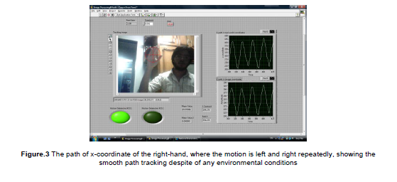
distances and in a safer manner. The experimental results supported the hypothesis by showing the
real time values, and thus the project met the design criteria.

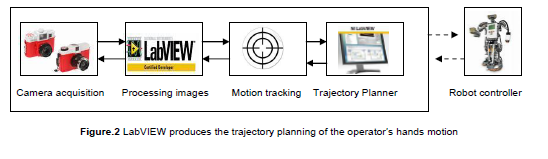
Figure.1 Robot imitates human motion
Introduction
The Vision-Based Robot Control technique, which is also known as “Visual Servoing”, is implemented
using binocular vision (two cameras) in a stand–alone configuration. The tracking system consists of
two cameras fixed together by a well known distance and connected to a PC via USB port. These
cameras would be in a stereo arrangement to provide complete 3D information about the scene.
Consequently, the depth estimation would be accurate The cameras are able to capture an image or
video at a frame rate of 30fps. LabVIEW 2009 is used to develop the path plan (position, velocity and
acceleration of the end-effector), where the acquisition of images is done by using the IMAQdx driver.
Further processing and analysis were implemented using NI IMAQ Vision. The cameras are
employed as a global sensor, and the robot would be separated from the framework, as it would be
controlled according to the operator’s movements in 3-dimensional space.
Trajectory Planning Algorithm
The difficulty of the Tracking algorithm is to implement a smooth tracker for the operator’s hands
motion, which has unpredicted motion and irregular shape that cannot be detected by pattern
matching or blob detection. Thus, an image subtraction algorithm is used in this project to recognize a
moving object according to its motion. The major reason for using this algorithm is that it is simple and
can be implemented with limited real-time processing capabilities for each camera, and then the
processing time for both cameras would be minimized. And it turned out to work acceptably well.
Camera acquisition Processing images Motion tracking Trajectory Planner Robot controller
The algorithm starts by choosing two regions of interest (ROI) which will be the tracking boundaries
for each hand. There was no need to use color formats (i.e. RGB) which may increase the processing
time unnecessarily, thus all processed images were converted to grayscale type. The cameras should
acquire at the beginning a background image, then it will be subtracted from each processed frame to
give a clear image of the moving object. After that, simply the previous frame image will be subtracted
from the current one. The result of the two successive subtraction operations will only show the
moving object on the framework of the image.
The mean value of the resulting image is determined and then multiplied by a pixel gain that is then
compared with a threshold value. This threshold value determines the beginning of the operation of
the tracking algorithm. In other words, the tracking algorithm will work if the mean value exceeds the
threshold value. After that, there would be four real time processing stages: 1. Segmenting the image
such that the object only appears as a set of white pixels, 2. Implementing a morphological filter to
remove any noise in the image utilizing erosion technique, 3. Calibrating the image in order to
transform its coordinates to the real world coordinates including the scaling factor, 4. Determining the
position of the object by calculating the centre of energy of the filtered image for each region of
interest. This position is then converted to the real world coordinates according to the applied
calibration rule. Finally, the determined X and Y coordinates can be indicated by overlaying a circle on
it with a noticed color.
Using numerical techniques, the coordinates’ values are differentiated once in order to get velocity,
and twice for acceleration. These outputs can then be used in an inverse kinematics algorithm to
control the motion of the robot joints.
Stereovision technique
Each camera is connected to a separate frame grabber where neither the cameras nor the frame
grabbers are synchronized. The IMAQ Start VI is called almost simultaneously for both acquisitions,
meaning that the next available frames from both cameras will be displayed. This mode acquires
images at a rate of 30 fps per interface since the cameras are connected to separate frame grabbers.
This mode can be enhanced by using another type of cameras (more expensive) to be 15 fps per
camera, but the results were acceptable compared to this approach.
It is relatively simple to implement a depth perception using any custom algorithm to get the best
results for the application. With the two cameras, each will follow the tracking algorithm in order to
detect the object, and then the pixel coordinates from both images will be compared, and finally a
stereovision triangulation algorithm would be applied translating the pixel position discrepancies into
distance and size. Consequently, the depth coordinate (z-axis) would be monitored using a graph
indicator referenced from a pre-initialized value, which refers to the real world coordinates.
LabVIEW was the best software for implementing an image processing, computer vision, and
visual servoing applications in real time
Most of image processing and computer vision applications implemented using C programming, but
stereovision applications would be very complex in its implementation and troubleshooting. So, IMAQ
Vision and LabVIEW were used for initial design and testing. Advanced signal processing features of
LabVIEW, such as filtering, significantly facilitate the program implementation. Moreover, the FPGA,
Real-time, and motion modules will conclude in a very efficient visual sevoing system working in real
time. Consequently, LabVIEW and National Instruments products are the first choice for all visual
applications.
