- Document History
- Subscribe to RSS Feed
- Mark as New
- Mark as Read
- Bookmark
- Subscribe
- Printer Friendly Page
- Report to a Moderator
- Subscribe to RSS Feed
- Mark as New
- Mark as Read
- Bookmark
- Subscribe
- Printer Friendly Page
- Report to a Moderator
Contact Information
University:China University of Mining Technology (Beijing)
Team Members (with year of graduation): LingKun Chen(2019) Yu Ban(2015) Zhao Wang(2015)
Faculty Advisers: JianWei Zhao
Email Address: wangz0506@sina.com banyukobe@foxmail.com
Submission Language: English
Project Information
Title:Mars Exploration Robot, Digger
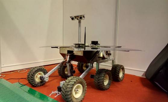
Picture 1 Mars Exploration Robot
Description:
The Digger in this project is a multi-wheeled mobile robot aiming to achieve explorative tasks on the surface of Mars. As the third generation Mars exploration robot model in the research group which our team belongs to, this digger shows high ability in exploring unknown places with the help of laser radar system and visual identity system that are applied and developed by our team on this model. Being benefit from LabVIEW and myRIO, the development period of this latest Digger was shorten dramatically comparing with the time cost of our previous models that are less functional and having relatively lower performance level.
Video Link:https://www.youtube.com/watch?v=EmtLdu-X4jY&feature=youtu.be
The used tools in this project are list as following:
NI myRIO--1900
LabVIEW 2014
LabVIEW Real-Time Module 2014
PID and Fuzzy Logic Toolkit
The other Hardware fits applied on the Robot and are necessary to be mentioned include:
Faulhaber2342L012
AVAGOHEDS-5540-I12
Products:
NI myRIO--1900
LabVIEW 2014
LabVIEW Real-Time Module 2014
PID and Fuzzy Logic Toolkit
The other Hardware fits applied on the Robot and are necessary to be mentioned include:
Faulhaber2342L012
AVAGOHEDS-5540-I12
PID motor drive module
The Challenge:
It is a common sense that power supply is a prerequisite of any human activity on Mars. The most likely primary power source for human missions on Mars or near-term settlement is solar power. However, the power supply system need to be designed thoughtfully in further to support a variety of potential power requirements of the robot according to its tasks.
Secondly, to guarantee the safety and controllability, the movement speed of the robot is supposed to be relatively slow. While the motion performance of the robot depends largely on its mechanical structures, therefore great attention has to be paid on the design and improvement of the robot’s mechanical structures in our work.
Finally, intelligence is one of the main concepts of the design of this Digger, to realize this function, visual data gathering equipments and local environment sampling fits should be loaded and assembled reasonably.
The Solution:
Recall that the aim of this project is to develop a robot that works in extreme environments and in a model that host computer is involved to control movements according to the real time environment monitoring. Our intensions were carried out and presented by the outcome Digger shown in Fig. 1 which contains characters as following:
1) Powered by solar panel, which greatly improves the robot's standby performance.
2) Aluminum alloy frame with high strength and light weight, which reduces the burden of the motor and helps to extend the standby time.
3) The chassis is enclosed, which is effective in protecting the electrical equipments and is more suitable for field operations.
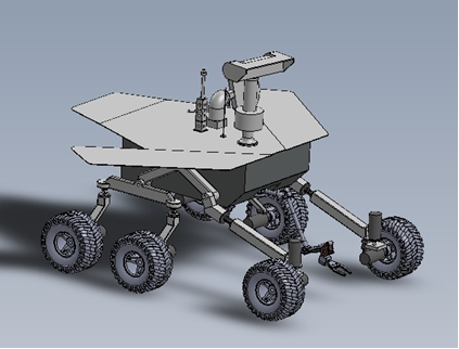
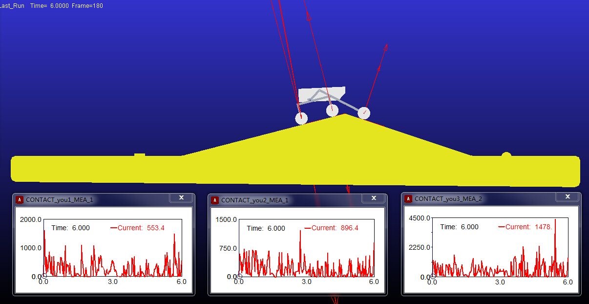
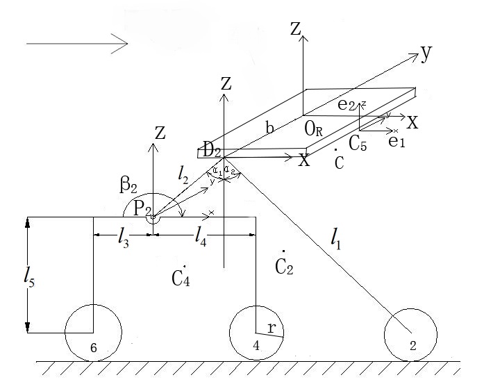
picture 2 Simulations of Mechanical Devices
More detailed illuminations about modules on the robot are presented as following:
1. The control system
The Mars robot mechanical structure is designed based on the theory of structural mechanics and dynamics considering the complex unknown rugged terrain on Mars.The structure of the robot has been simulated by SolidWorks.
Picture 3 simulated by SolidWork
In accordance with the general design requirements of Mars robots, closed loop DC motor is adopted. Besides, a dual DC motor driver is developed by using NI myRIO, based on which the PID parameters in the algorithms are optimized. The Faulhaber gear motor with encoder 2342L012CR (12V, 17W, large output torque, with reduction ratio at 64:1) is used. Appropriate feedback control methods are applied to improve the operation accuracy.
According to the characterristics of multithreading in LabVIEW, We put several major functional modules in the different thread running alone.
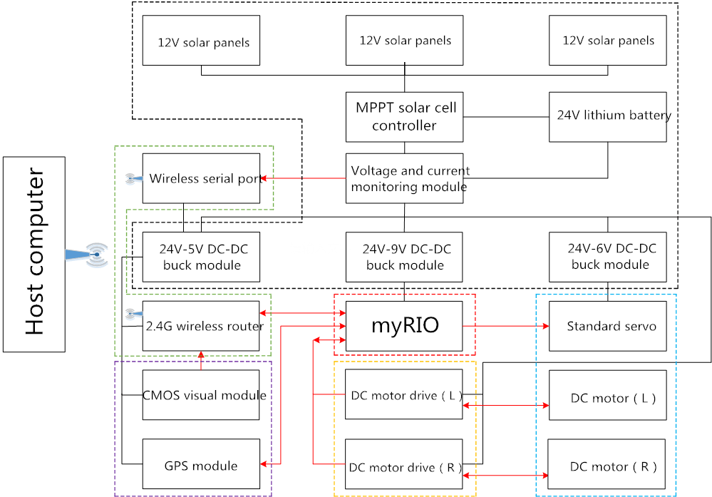
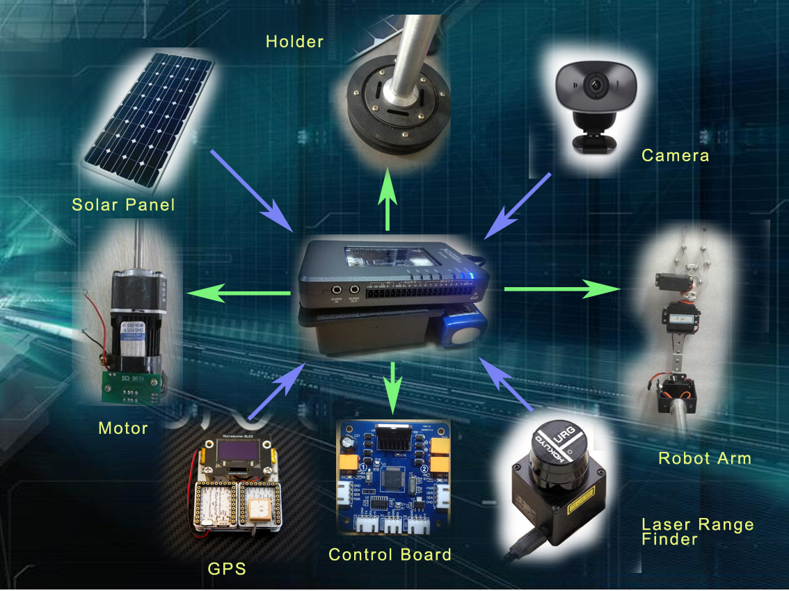
Picture 4 Electric System
motor (Faulhaber2342L012)
Performance parameters:
Working voltage 12V, motor no-load speed 8100 rpm. The final output speed of the belt is 120 rpm.. (voltage can be overloaded to 24V use, rotate speed is 240 / minute.)
The motor diameter is 23mm, the length of the motor is 42mm., the total length of 30mm. is 85mm (excluding the output shaft length).. Output shaft diameter is 6mm. axis length 35mm.
The motor is up to 40W at the 24V voltage, and the torque is 100KG.CM (10N.M), and the continuous torque is 40kg.cm.
The reducer for the full steel planetary reducer, the reduction ratio of 64:1.
The weight of the motor is 235g.
Encoder (HEDS-5540-I12 AVAGO)
Performance parameters:
Output type: orthogonal, with scale angle (increment).
Number of pulses per revolution: 512
Voltage: 5V.
myRIO-1900
Performance parameters:
Xilinx Zynq-7010 core chip of Ni myRIO-1900. The chip integrated the 667 MHz dual core arm cortex-a9 processor and contains 28K logic unit, 80FPGA DSP slices, 16 channel DMA. Ni myRIO-1900 built-in 512MB DDR3 ram and 256MB of non volatile memory and, in addition, can be connected to the external USB devices through the Ni myRIO-1900 integrated USB host.
Camera (moons S608)
Performance parameters:
Pixel: 6000000.
Photoreceptor type: Sensor COMS
Lens: 5 lens
Support resolution: 320*240, 640*480
The maximum frame rate of 30 frames per second:
Color: about 65000 color
Holder
Two DS3115MG digital servo, 6V power supply
Horizontal limit: +90, -90
Vertical ultimate angle: +70, -10
robot arm
Four digital servo DS3115MG, 6V power supply
PID motor drive module
Performance parameters:
Rated voltage: 24V
Maximum power: 120W
Communication interface: COMS level UART interface, UART RS232 interface, I2C interface, USB serial port
Motor interface: 2 motor drive interface, 2 encoder interface
2. Sensing
1) Radar Scaning
The Hokuyo laser radar is used to detect the road situation that managed by LabVIEW. Compare to others software benefits of LabVIEW is that we can use the same technology in the final phase of experimental development, the deployment phase and that that it offers easy and seamless integration with legacy and traditional benchtop, stand-alone instruments commonly found in research labs.

Picture 5 Control Panel
In the LabVIEW programming, an Event Structure which contains multiple conditions is used. In the case of Timeout, a Shared Variable, which was assigned to be the latest LiDAR data by the NI myRIO, would be checked. A Compass Plot thereby could be created according to the angular separation concepts using the LiDAR data, i.e. the distance measurement results. The created Compass Plot would graphically depict the radial distribution of the measurements that had been acquired by the URG-04LX.
In the case of LiDAR Configuration, the program checks if any change happened on any element in the LiDAR Configuration Cluster, and the inspection results then would be used to construct a new object of type Configure Measurement State, which sets the Measurement Parameters in the class to the numbers that are specified on the Front Panel.
This object is placed in an array followed by a Read Measurement State Object. The array is supposed to be transmitted using the Transmit Classy States VI.
The programming introduced above actually attempts to conduct the myRIO to carry out operations in a certain order: it would firstly read the new LiDAR configuration parameters we've specified and initialize the URG-04LX to measure under the work-state setting with these parameters; After that, the myRIO should return to the Read Measurement state so that the acquired data are ready to be transmitted to the host machine via the Shared Variable.
2) Visual Transmission
When approaching to a physical object, the Digger is commanded to seize the object using the position information acquired by vision system. The Robot is equipped with two CMOS vision modules bounded with mechanical holder and an omnidirectional vision system. The Binocular vision technology imitates human binocular stereo perception, and it is implemented by using two cameras at the same time to collect images of the same scene. According to the scene in different camera imaging parallax, the depth of the space object is obtained, so as the information that are required to rebuild the scene in 3D. The Vison Assitant is used to carry out the process, when it found any object staying in near view, the manipulator on the Robot will automatically focus on it and grab it.
3) Environmental Monitoring
In order to monitor the environment states surround the Robot, the light sensor on chip BH1750FVI , the digital temperature sensor single bus DS18B20 and humidity sensor DHT11could be used for environmental data real-time feedback and display.
3. Power Source
Based on a comparison research on the performance of several popular photoelectric conversion materials, considering the power requirements of the Mars robot as well as the feasibility of each possible power supply scheme, the photovoltaic power system was chosen and interpreted as following:
1) The main body consists three monocrystalline silicon solar cell phalanx series in parallel; each series is of 12V.
2) The perturbation method of observation was used in the MPPT algorithm.
3) Solar photovoltaic energy storage component in the system is the lithium-ion battery pack with storage capacity at 24V.
4) Buck circuit module was used in the internal integrated circuit for power supply; lithium battery is used to make sure that the Mars robot works regularly.
5) Voltage and current detectors are applied for voltage sampling and inspecting the output current of PV array, respectively. The detected data are displayed on the LCD panel in real time, and are also sent via wireless router serial port to the host machine for testing and output power calculation.
solar powered plate
Performance parameters:
Dimensions: 512mm*260mm
Material: single crystal silicon a plate
Power: 20W*3 (when enough)
Voltage: working 17.6V, open circuit 21.6V
Current: working 1.14A, short circuit 1.29A
Weight: 1.75kg
Working temperature: -40/+85
solar energy vehicle power (LT8705)
Performance parameters:
Volume: length 59mm wide 106mm thick 22mm (including shell)
Input voltage: 8-32V
Output voltage: 1.2-32V
Input current: 0-20A
Output current: 0-20A
Constant current: 2-20A,
Output power: maximum continuous 200W, instantaneous 300W (10 seconds)
Efficiency: measured 9V or 15V input, 12V output, 3A
Voltage adjustment rate: better than 1%
Ripple: less than 10mVp-p
Future Work:
Part of function of the Mars exploration Robot has not been developed, that some parts is not optimized. It only takes our 4month that more function will be accomplish in the future.
1. We will optimize the whole software architecture that is only implements the function of program which also need to be further improveed.
2. The relative modular communication system will be developed that it can deal with more real environment, increase the communication distance.
3. More features are needed, power remote monitoring and automatic pathfinding, etc.
4. More humanized human-computer interaction interface.
Attach Poster
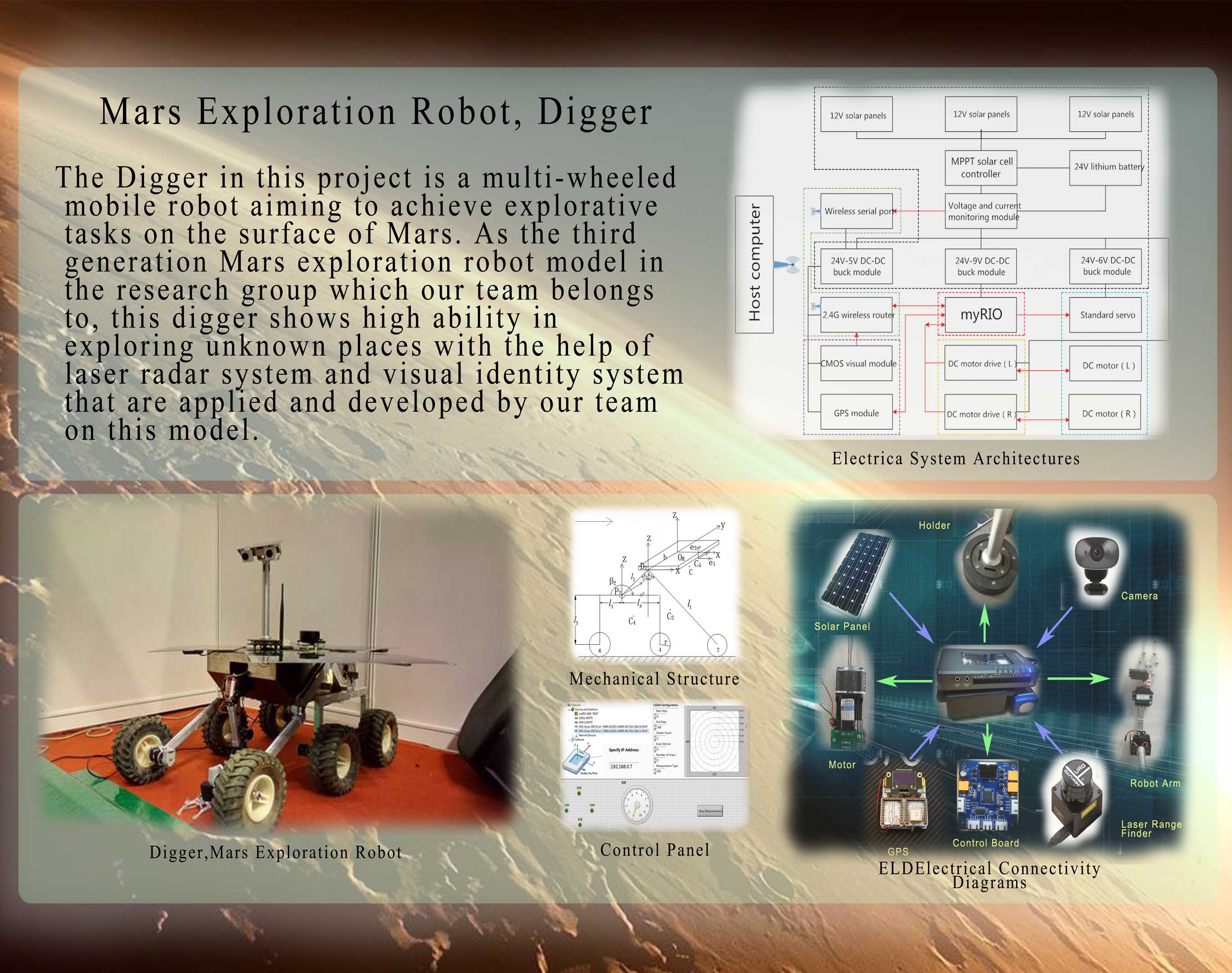
Picture 6 Poster
