- Document History
- Subscribe to RSS Feed
- Mark as New
- Mark as Read
- Bookmark
- Subscribe
- Printer Friendly Page
- Report to a Moderator
- Subscribe to RSS Feed
- Mark as New
- Mark as Read
- Bookmark
- Subscribe
- Printer Friendly Page
- Report to a Moderator
Contact Information
University: Konkuk University, South Korea
Team Member(s): Byoung-Jin_Lee, Seung-Jun_Lee
Faculty Advisors: Prof. Sangkyung Sung; sksung@konkuk.ac.kr
Email Address: schumir_@hotmail.com, hopengman@naver.com
Description:
Our target platform is a Rotary Unmanned Aerial Vehicle (RUAV). For the implementation of realtime autonomous flight system, the RUAV is equipped with navigation sensors such as the GPS (Global Positioning System), IMU (Inertial Measurement Unit), photo sensor for getting main rotor RPM data, barometric altimeter, and onboard realtime controller board, NI-sbRIO and further necessary accessories. The considered rotary vehicle (helicopter) has weight about 4.1kg, installed with 12cell Li-Po battery (5000mAh x 2) and overall length of about 1.5m, main blade diameter with 1.78m.
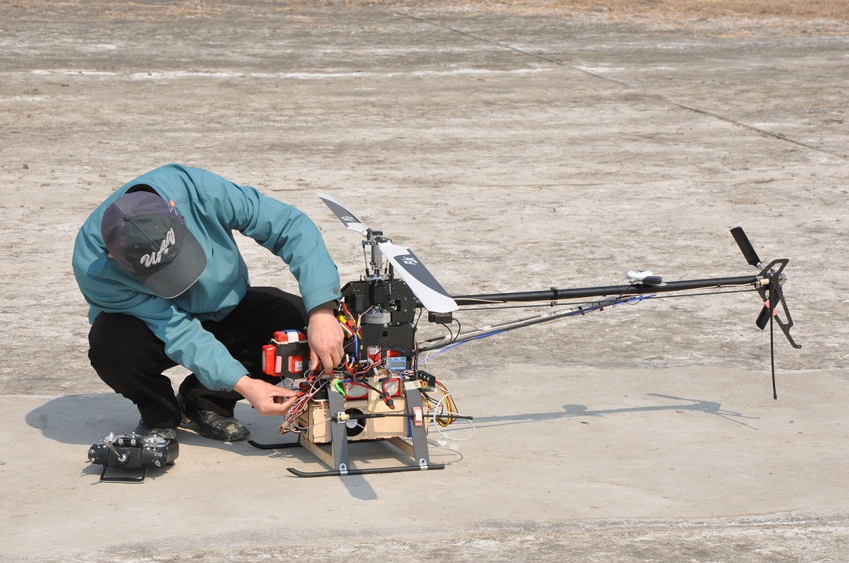
Rotary UAV platform on ground
Products:
NI sbRIO-9602
NI 9870
LabVIEW 8.5
NI-RIO 2.4.1
The Challenge:
Onboard avionics system within UAV is very complicated especially for the automatic flight. Also due to its operation in 3 dimensional space, it is subject to crash when losing stability of the vehicle attitude. Note that the system dynamics of RUAV is inherently nonlinear and unstable, thus is prone to get unstable.
In this background, to achieve an onboard navigation, guidance, and control system, a highly reliable, realtime embedded system with sufficient computing capacity is needed. From functional point of view, precise yawing (directional pointing) capability under stabilized attitude and trajectory following capability are essentially required, thus the main flight control computer (FCC) must have capability to integrate various navigation sensors, DAQ, PWM servo control, and fast data processing unit. For flexible communication with ground control station (GCS) and flying UAV, communication enabling data network is also recommended.
Here, we listed fundamental considerations of this project.
We need:
1. the high performance embedded system that is easy to develop.
2. the real time monitoring system to prevent the accidents.
3. to acquire the sensor data in high rates for the high dynamic RUVA control.
4. to develop attitude control and autopilot system to enable operation without a trained RC manual pilot
5. the light hardware. If it is heavy, aircraft can’t fly or has very limited flying time!
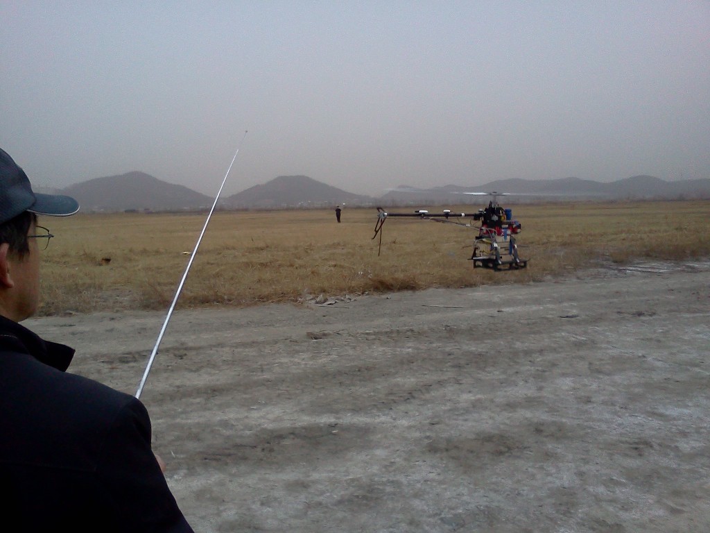
Manual Flight by RF Remote Controller
The Solution:
1. DSP or ARM processor based by C language is very famous in embedded system. But the composition of their development environment is not simple. The development tool is generally difficult for the beginner. And the library is not well-supported or hard to utilize. For a more simple and convenient access to embedded system development, we have chosen NI-sbRIO and virtual instrumentation based platform.
sbRIO can be developed in LabVIEW GUI programming environment. It is easy to develop the algorithm and use H/W, S/W library with sufficient tooboxes. We know that this embedded system is more expensive than other and LabVIEW is heavier than other development tools. But using this system, we've saved more time and reduced engaged members in embedded part. As listed, only two student members with the advisory professor have been involved in this project.
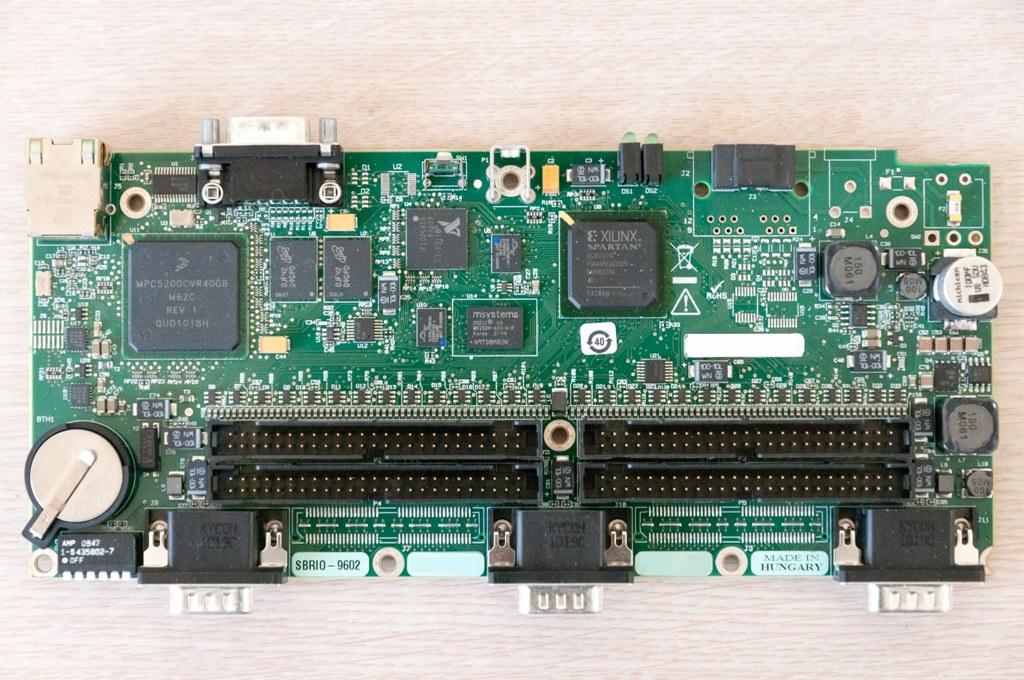
NI-sbRIO 9602
2. For operating UAV, GCS (Ground Control System) is also needed. GCS controls aerial vehicles flying paths, commands operations and notices the situation of UAV in realtime manner to developer or commander. Thus GCS is very important part in constructing the flight system. In LabVIEW environment, using the LabVIEW front panel, we could easily develop GCS panel and required interfaces. The front panel shows all of the RUAV flight data and provides interface to change the settings and command values. Its response is very fast, so we use those function of the front panel for the in-flight gain tuning of PID controller in the early test phases. Graphical interface is very simple and easy, which is regarded as the most fundamental and advantageous feature of LABVIEW.
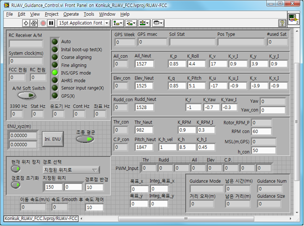
Front panel of GCS
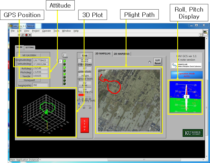
Flight Data Display Window
3. Though sbRIO has fast main processor (400MHz), many sensor data can make some congestion problems. For the control of high dynamic system, we need high update rate of sensor data.
In our flight system, IMU (Inertial Measurement Unit) is the most essential sensor. The IMU outputs data packet in high rate (up to 100Hz), and each packet has about 100byte data. For realtime operation, it requires very high processing capability with big packet size. It takes many resources in sbRIO main processor. Therefore we reduced the calculations for sensor data in the main processor via packet processing optimization for the guidance, navigation and control calculations. Most of all, sbRIO has also FPGA. FPGA operates the high fast logic gate calculations. So using FPGA, we can share the data handling burden in the main processor.
To use sensor data, several low level calculations are needed. Most of the calculations are bit or single byte tasks so these low level signal processing parts could be operated in FPGA side. Using this method, RTOS in main processor only needs to convert the rearranged bit data into informative data to be used in the high level logics, which reduced the total computing burdens in the main processor.
.png)
Sensor Data Flow from FPGS to RTOS in Main Processor
4. Weight is one of the most important parameter in aerial vehicles. The sbRIO is supposed to be a proper choice as it weighs less than 200g. In addition to that, we reduced the weight of other devices. Case material is wood. Wood is light but not so strong material. But it is easy to cut and cheaper than other material. And we cut all of cable in this case shorter. Only needed devices to automatic flight are putted within the case. For low power consumption, all optional parts (LED, beep…) were detached.
The flight system approximately needs 20W. According to the onboard device specifications, we designed the power supply to convert battery voltage (22.2V) to 12V, 5V and 3.3V. To make only needed voltage and ampere, our designed power supply succesively save the wasted power consumption. This enabled to use FCS (Flight Control System) with smaller battery capacity.
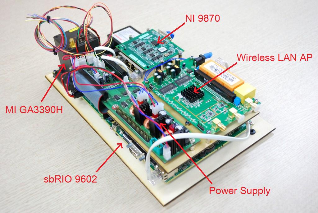
Total Hardware Configuration
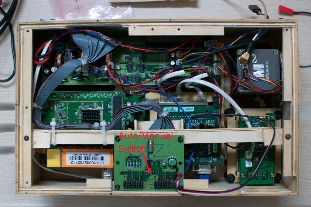
The sbRIO is installed in the bottom layer of case. In top layer, NI-9870, WLAN AP (Access Point), and power supply are installed. NI-9870 is able to communicate with sensors via RS-232. An off-the-shelf WLAN AP module is used for connection with GCS. And Auto/Manual Switch module converts the actuator signals between Auto/Manual commands. If RUAV is in dangerous situations during Auto-Pilot mode, pilot can control the vehicle using the Auto/Manual Switch.
.png)
Data Flow of FCS
The adopted sbRIO 9602 doesn’t have the analog to digital converter. So we add Amtel AVR to sense the battery's analog voltage. sbRIO 9612 have this function, but is 70g heavier than 9602. Also it consumes more power than 9602. The pre-processed data in FPGA are sent to RTOS in the main processor. The Controller in RTOS runs various high level algorithms such as coordinate conversion, trajectory generation, guidance logic calculation, PID controller output generation and transmit/receive control for data communciation. The generated control signals for UAV attitude/motion control are sent to FPGA to invoke PWM digital signal for actuator driving. PWM signals are input to main rotor motor or servo motors. Finally, all the necessary information for flight control are transmitted and monitored at GCS display.
Flight Test & Conclusion
Landing and take-off are dangerous operation to all of flight vehicles. For the safety of vehicle frame and FCC board during VTOL operation, human pilot controlled the RUAV while landing and take-off. Except two operations, all movements are controlled by auto-pilot. For the analysis, all necessary sensor data are saved in flash memory of sbRIO. At the same time, essential navigation data like position, attitude, and velocity are sent to ground station thus, GCS computer can show the flight path and vehicle attitude in realtime manner. Besides, using the additional GCS data interface, we could observe the RUAV conditions and command the operations to RUAV.
For autopliot demonstration, we will show 3 flight test results as the following:
- hovering and yawing flight (attitude stabilization)
- low altitude, droplet flight (attitude control + altitude control + waypoint guidance)
- infinity flight ^^ (attitude control + altitude control + waypoint guidance)
The first result shows hovering and yawing motion control of rotary UAV. The yawing motion at a fixed position is the key exclusive functionality of rotor compared with fixed wing aircraft. Yet, as the rotor dynamic model is inherently unstable, it is very difficult to keep aerial vehicle stabilized. Thus this hovering and yawing flight is the most fundamental requirement during rotory UAV development. After applying PID control to roll, pitch, and yaw dynamics, we could achieve a successful result as the following. Plz observe the stabilization under windy environment (7~9 m/sec wind speed condition).
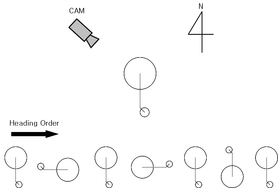
Heading Control and Turning Order
Next figures show the ‘Water Droplet’ flight path and its path error from programmed reference trajectory. This operation is repeated 4-times. The average path error from reference is about 2 meters, which demonstrates excellent position accuracy of RUAV. In this case, flight trajectory is relatively smaller and altitude is lower than other paths, which could enable us to observe more easily the flight.
.png)
.png)
Flight Path(Left) and Position Error(Right)
Flight Test Video(Left) and GCS Display(Right)
Finally, the following figures show the ‘Infinity Symbol’ flight path and path error. This operation is repeated 2-times. The average path error is about 3 meters and maximum about 8 meters. Note that paths are much bigger than ‘Water Droplet’ flight path. In this path, the scheduled flight velocity is faster than the previous droplet case, i.e., 10m/sec. This path was used to observe the control logic performance during high speed flights, and simultaneously orienting performance during circular interval flight.
.png)
.png)
Flight Path(Left) and Error(Right)
Flight Test Video(Left) and GCS Display(Right)
- Mark as Read
- Mark as New
- Bookmark
- Permalink
- Report to a Moderator
Hello there,
Excellent project!!
Thank you so much for your project submission into the NI LabVIEW Student Design Competition. It's great to see your enthusiasm for NI LabVIEW! Make sure you share your project URL(https://decibel.ni.com/content/docs/DOC-16504) with your peers and faculty so you can collect votes for your project and win. Collecting the most "likes" gives you the opportunity to win cash prizes for your project submission. If you or your friends have any questions about how to go about "voting" for your project, tell them to read this brief document (https://decibel.ni.com/content/docs/DOC-16409). You have until July 15, 2011 to collect votes!
I'm curious to know, what's your favorite part about using LabVIEW and how did you hear about the competition? Great work!!
Good Luck, Liz in Austin, TX.
- Mark as Read
- Mark as New
- Bookmark
- Permalink
- Report to a Moderator
Excellent work!
Fully embedded onboard autopilot system using NI-sbRIO and sensors despite many contraints on power, weight and size.
Included project files,, also amazing and professional with outstanding completeness.
I appreciate your enthusiasm and efforts.
- Mark as Read
- Mark as New
- Bookmark
- Permalink
- Report to a Moderator
Thank you for your attention and great efforts on this projects.
I`ll cross my fingers for your good results and keep better solution with LabVIEW and embedded sbRIO of your application, thanks!
- Mark as Read
- Mark as New
- Bookmark
- Permalink
- Report to a Moderator
very Great job
I would like to have a look on the code
- Mark as Read
- Mark as New
- Bookmark
- Permalink
- Report to a Moderator
Dr. Alaa
Thanks for your good job, its great work, it gives me the chance to do something close to your work, now I design a PID control system and navigation, also guidance law, but I am still working in a code that how to update the waypoints after certain condition like a circle around each waypoint but still suffering to do it using Labview, so please if you have an advice with an example code to use it in our project I appreciate your help too much.
