From 04:00 PM CDT – 08:00 PM CDT (09:00 PM UTC – 01:00 AM UTC) Tuesday, April 16, ni.com will undergo system upgrades that may result in temporary service interruption.
We appreciate your patience as we improve our online experience.
From 04:00 PM CDT – 08:00 PM CDT (09:00 PM UTC – 01:00 AM UTC) Tuesday, April 16, ni.com will undergo system upgrades that may result in temporary service interruption.
We appreciate your patience as we improve our online experience.
University of California, Berkeley
Students:
Daniel Talancon (ME Ph.D. 2014)
Toby ricco (ME Master's 2014)
Carson Schulze (ME Master's 2014)
Nick Okita (ME Bachelor's 2013)
Faculty Advisers:
Prof. Dennis Lieu (3D Modeling and Motor Design)
Prof. Benson Tongue (Vibrations and Dynamics)
George Anwar (Labview and Controls Lecturer)
Email: instar@lists.berkeley.edu
Site: http://instar.berkeley.edu/
Submission Language: English
The INSTAR go-kart is an early prototype of a flywheel-electric hybrid vehicle. The technology applies best to the market of city vehicles with frequent start and stop cycles—the prototype will eventually be scaled from a go-kart (figure 1) to a Daimler SMART car application. The vehicle features independently driven rear wheels, traction control, and an electronic differential in addition to the flywheel system. The differential was achieved by a torque-splitting control algorithm to modulate current to each of the independently driven rear wheels; traction control was realized by means of speed matching the rear wheels to the front wheels.
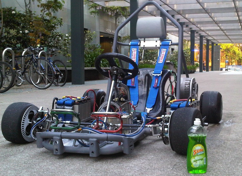
Figure 1–The INSTAR prototype vehicle
• (1) NI cRIO-9076 compact microcontroller
• (1) PS-15 Power supply (781093-01)
• (1) NI 9207 analogue input module (with 778676-01 connector block and 778621-01 cable)
• (1) NI 9263 analogue output module
• (1) NI 9853 CAN bus module**
• (1) NI 9403 I/O module (with 778676-01 connector block and 778621-01 cable)
Major Vehicle Components
• (2) 8 kW Brushless DC Motors (Mars Motors)
• (2) 72 Volt, 180 Amp Brushless DC Motor Controllers (Sevecon)
• (6) 12 Volt Sealed-Lead-Acid Batteries
• (1) Indoor Go-Kart Chassis
• (1) 5-Point Safety Harness
• (1) Custom-fabricated roll bar
The two key features of a truly sustainable future are both responsible energy production and smart energy consumption. Improving our energy efficiency has become an important focus area in reducing our energy demand, and it will require addressing this effort from multiple directions if it is to have a major impact. The ability to both capture and reuse currently wasted energy presents an exciting opportunity for inter-disciplinary innovation geared towards increasing system efficiency, especially in transportation and manufacturing, areas that consume over 70% of worldwide energy production according to the European Commission’s World Energy, Technology and Climate Policy Outlook 2030.
The INSTAR system is a high-power, cost-effective, flywheel energy storage system (FESS) with potential future application in efficient manufacturing processes, power management, and immediate energy capture and reuse applications in improved electric and hybrid-electric vehicle regenerative braking capabilities. Large machine tools spin at over 5,000 RPM while active, but must be stopped after each process for safe access to the machined part. This large rotational energy is simply dissipated between parts, but can be captured and reused to lower the overall energy demand of the manufacturing process. Highly repetitive and predictable, this area is very promising for short-term, controllable energy storage. Regenerative braking in hybrid and fully-electric vehicles is an emergent technology that has successfully increased vehicle fuel economy by utilizing the bi-directional energy flow capability of electric motors to capture and reuse the vehicle’s kinetic energy normally dissipated during braking. However, regenerative braking has been hampered by current chemical battery technology; only 40% of the available braking energy is captured and reused, limited by the relatively poor charge rate of popular battery technologies, including lithium-ion. Excess energy the batteries cannot accept is still simply lost. Figure 2 shows the internal components of the first iteration INSTAR system.
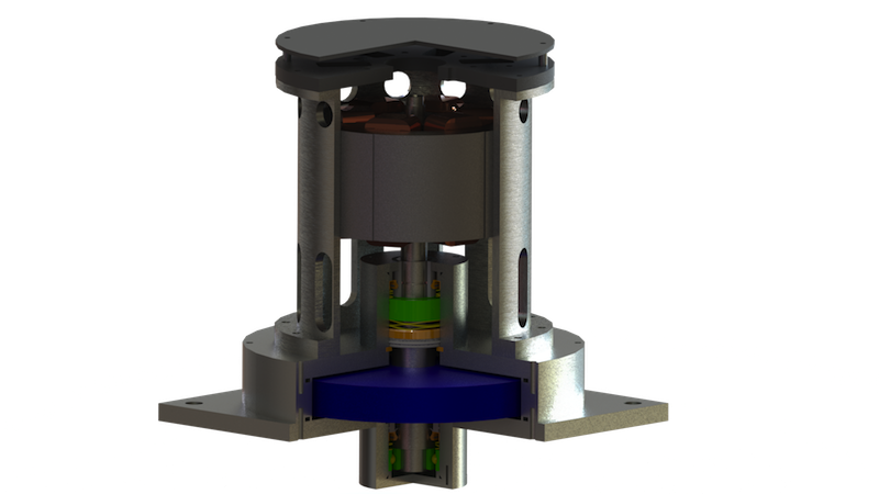
Figure 2–The INSTAR system: flywheel (blue) and integrated motor (copper and grey)
Flywheels are mechanical batteries not limited by the cell chemistry kinetics of current battery technology and can accept energy at a substantially higher rate of power flow. This superior power rating allows the flywheel energy storage system to capture much more of the available braking energy generated during the rapid and repeated accelerations of typical urban driving. Coupled with a brushless DC (BLDC) motor, the INSTAR system efficiently reuses the captured flywheel energy by either powering the electric drive motors for vehicle acceleration or by charging the chemical batteries at an optimized rate for extended vehicle range. This innovative power management scheme requires only short storage periods, the key to a cost-effective, reliable system design. Compared to the regenerative braking systems on PEVs and HEVs today, the addition of the INSTAR flywheel energy storage system (FESS) will allow for 50% more braking energy to be both captured and reused at minimal added cost, extending total vehicle range by 10-15% in our vehicle simulations.
NI LabVIEW software combined with the cRIO has been highly effective for the development of our flywheel-electric vehicle. The hardware and software is easy to set-up, learn, has many built-in tools, and works well in stand-alone applications. Most importantly, the National Instruments microcontroller system and its components are very modular. All of these features combined with easily custimizeable GUI's (Graphical User Interface) to work with the control systems make NI hardware/software packages very attractive solutions for prototyping. Figure 3 shows our vehicle controls GUI.
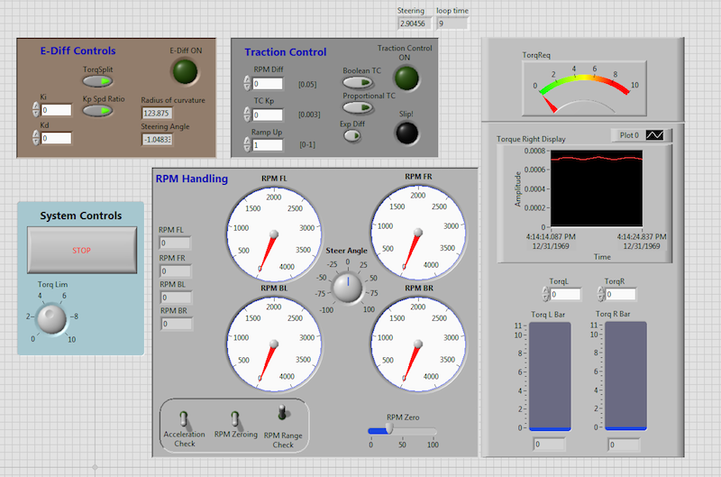
Figure 3–First iteration of vehicle system user interface
The vehicle has numerous sub-systems: the traction control system (4 sensors), the electronic differential system (5 sensors), and the flywheel system (multiple current, voltage, vibration, and temperature sensors). As with typical prototypes, the demand for additional sensors and input/output (I/O) channels has increased beyond expectations. Labview microcontrollers allow us to add I/O modules of many different types (voltage, current, analogue, digital, etc.) with very little additional cost to the entire system. Additionally, when a module is added and our system expanded, no new code or modifications are required to maintain all of the functionality of the control code that was already written. Figure 4 is a highly-simplified block diagram of the control loop that will be employed on the INSTAR kart prototype and Figure 5 shows a sub-VI of the electronic differential sub-system.
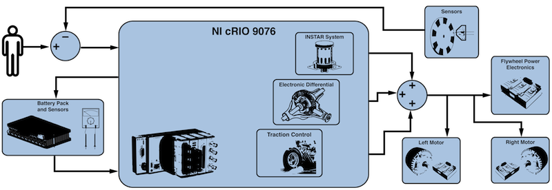
Figure 4–Overview of the traction, differential, and flywheel control systems
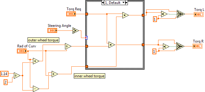
Figure 5–Sub VI component of the Electronic Differential System
Finally, the NI application builder allows us to program the microcontroller to boot when it receives power, making it a fully stand-alone system with no external computer controls necessary. In addition, in its stand-alone mode the controller is still able to log data to a usb flash drive—an immensly valuable feature when optimizing a system with a large number of sensors.
Although our research is focused on inertial storage, many students who have been in the research group have adopted the guidelines of a class project to apply to the vehicle in one form or another. As a result, the electric go-kart prototype has a fully-rendered model (E128 project, Video 1) and advanced vehicle controls (ME135 project, Video 2).
Video 1–E128 Vehicle rendering: explode, collapse, and power flow diagram
Video 2–Early test run of traction control
The project is still under development—the second prototype of the flywheel will be manufactured in June of 2013. The prototype vehicle's twin motor, traction control, and electronic differential systems are functional but in the revision phase.
The research concept being validated by the kart prototype vehicle was created in late 2009 . Assembly of the go-kart prototype platform began in Spring 2010. Significant funding was just awarded to our research group in Spring of 2013 and production of a fully-functional flywheel is in progress and expected to be finished by end of 2013 or sooner.
The following items are works-in-progress and are continuously being revised and improved:
•Traction control smoothness
•Electronic differential user settings (speed variable torque splitting, race/comfort torque splitting)
•Regen brake control and blending
•Move code from microcontroller to integrated FPGA to decrease looptime
•Fit and finish—build PCB's, isolate and shield electronics, locktite hardware
•Flywheel control system
•Flywheel data acquisition and optimization
