- Document History
- Subscribe to RSS Feed
- Mark as New
- Mark as Read
- Bookmark
- Subscribe
- Printer Friendly Page
- Report to a Moderator
- Subscribe to RSS Feed
- Mark as New
- Mark as Read
- Bookmark
- Subscribe
- Printer Friendly Page
- Report to a Moderator
Foot Pressure Monitor Phase II
Please complete the following information
Contact Information
University and Department: North Carolina State
Team Members: Jacob Griffith, Jihad Nance, Mark Rakowski, Jason Snider
Faculty Advisors: Dr. Ozturk, Dr. Cartee
Primary Email Address: m2j1r0@hotmail.com
Project Information
Project Title: Foot Pressure Monitor Phase II
List all parts (hardware, software, etc.) you used to design and complete your project:
Battery Connectors For DAQ - 196739-01 - National Instruments
12V Battery WKA12 -2.3F and Charger WK12V500 - Batteries Plus
15 Pin Serial connector - Radio Shack
12V Battery Connectors - Radio Shack
Belt - Marshalls
Heat Shrink, 9 Pin Dsub Connectors, Velcro - Radio Shack
Project Box - Radio Shack
Serial Cables 6ft Serial270 - CablesToGo
Printed Circuit Boards - Radio Shack
4:1 Multiplexers DG409DJZ - DigiKey
555 Timer - DigiKey
D- Flip Flops SN74S74AN - DigiKey
NAND Gates DM74S10N - DigiKey
XOR SN74LS86AN - DigiKey
Sandals - Payless
FlexiForce Sensors (8) - Phase I
National Instruments WLS - 9219 DAQ - Phase I
National Instruments Labview 8.5 SE - Phase I
Wire, Solder
9V Battery
Wood for Calibration
Describe the challenge your project is trying to solve.
The goal of this project is to synthesize a method of testing the pressure applied to the foot of a person walking at variable speeds. As a continuation of a previous project, we have a prototype device composed of four pressure sensors, an insole, and a bit of wood for a base. This is then connected via hardware serial inputs to a National Instruments DAQ board, with a LabView interface for viewing the data collected. The previous implementation shows that it is possible to record the static data of an individual standing on a flat surface, however our design needs an increased robustness in the form of dynamic movement. This project is sponsored by Carolon, with contacts being Dr. Hatice Ozturk and Dr. Lianne Cartee. Our team is made up of Jacob Griffith, Jihad Nance, Mark Rakowski, and Jason Snider.
As there is a prefabricated design base for this project, our goal will be to add additional capabilities over the original product. The major focuses are the implementation of a variable pressure monitor capable of reading data from an individual walking at a steady pace, so as to detect the pressure applied to the foot during the course of activity. A second goal is the implementation of a wireless unit so the subject is able to walk on a treadmill without the limitation of a wired system, which would increase the difficulty for a person with possible mobility limitations. Thirdly, the data collected must be stored in an easy to parse format so it may be used for insole fabrication or research beyond the time of collection. Additionally, our group will increase the weight tolerance on the sensors to accommodate a person of over 300 lbs, which is a more realistic weight limit for people with advanced diabetes. A further design goal is the extension of the apparatus to a second foot or more sensors on foot. This device should also be aesthetically pleasing; as having some minor, appeal would make the subject feel more comfortable using the system in a medical setting.
This project fulfils a major shortcoming in the care for those living with diabetes. With the frequency of diabetic foot amputations, it was proposed that the creation of adequate footwear could save not only limbs but also lives. While clearly in the developmental stage, the seemingly futuristic technology of an insole that responds to the wearer’s foot would be thought impossible but a few short years ago. Simple advancements in polymer technology will yield an overall improvement in the comfort afforded by an insole, however without dynamic variability there will still be pressure points leading to the same diabetic injuries. The combination of rapidly advancing wireless technology with ever-shrinking microprocessor leads to a system that is fully programmable while being small enough to be worn and carried by those stricken with diabetes. With the standard insole technology having seemingly hit a wall, the next frontier is that of the adjustable insole.
Describe how you addressed the challenge through your project.
The objective of this project was to design a system that collects pressure data at various points on the foot, which can later be used to relieve stress caused by excessive pressure on the feet of diabetics, who are unable to feel blisters as they develop due to nerve damage. The sponsoring company, Carolon, hopes to use this data to create socks and stocking that are custom fit to relieve pressure on diabetics, or can automatically adjust when pressure is too great at a certain point on the foot.
This project is an expansion of a design worked on last semester by other students. At the conclusion first phase of the project, the design consisted of four sensors inside a shoe insole, which was set on a board. The sensors were connected to a project box, which amplified each of the four sensors. There was variation among the sensors, so each sensor was calibrated using potentiometers within the project box. From there, the amplified voltages were read by the National Instruments data acquisition board. The data acquisition board was connected via wire to a laptop. The previous semester's team developed software to display the pressure on the laptop.
For this phase of the project, the number of sensor was expanded to eight to take more data from around the foot. In addition, the system was made mobile by changing making the link from the data acquisition board to the laptop wireless, and by setting the sensors inside an insole, which could be put inside a user's shoe. Several other changes were made to the hardware and software of the project, described later.
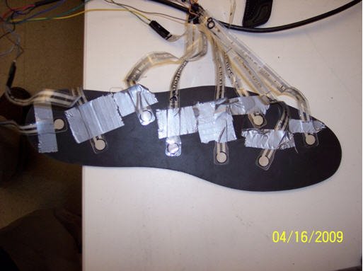
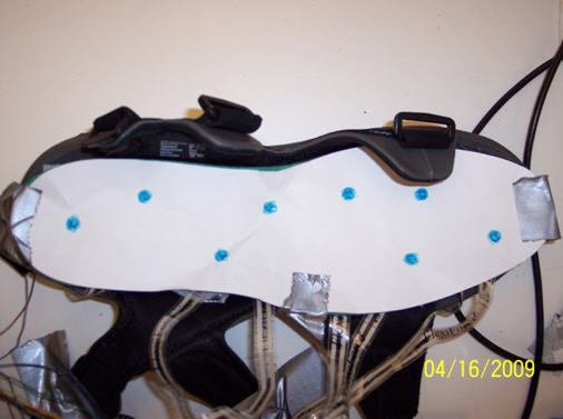
As mentioned, eight sensors were used to measure pressure on the bottom of the foot. These flat sensors act as resistors that change the value of their resistance based on the amount of pressure being applied. The sensors were secured inside a shoe insole to measure important points, such as the big toe, the heel, the arch of the foot, etc. The insole can then be placed into a shoe for the user to wear.
The output wires of the eight sensors are run from the shoe to the project box, which is attached to a belt for the user to wear around the waist. Inside the project box, each sensor input is connected to an op-amp that converts the input resistance to an amplified voltage in the range of 0V to about 3V.
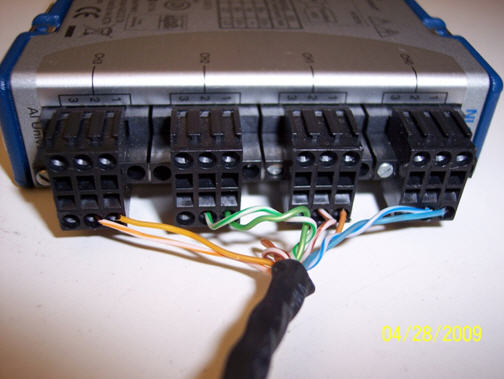
The data acquisition board had only four input channels for our eight sensors. Therefore, another circuit can be found in the project box, which switches between the set of sensors being read. At any given time, only two or three of the eight sensors are being read. The set of sensors being read changes about every 100ms, based on the settings of a timer circuit. The project box has four outputs to the data acquisition unit, one telling which set of sensors is being read, and three more giving the output of the amplified sensors.
The National Instruments data acquisition board and its battery pack are also attached to the same belt as the project box. As described, a wireless link is set up between the data acquisition unit and a laptop in an ad-hoc 802.11b Wi-Fi network. The laptop has National Instrument's Lab View software installed on it, and a new program developed by this semester's team. The software displays a diagram of a foot, with points corresponding to where the sensors are located that change color intensity based upon the amount of pressure on the foot, all in real time. After the test is completed, all the collected data for each sensor is displayed on a graph and is saved to a text file.
As it stands, the project was completed successfully and met all design requirements, but there are several possible ways future students assigned to this project could expand the design. First, there are a number of ways to change the hardware. Extra sensors could be added by generating four states (and therefore, four sets of sensors) instead of three. A resistor network could be used to differentiate between the four states. The frequency at which the system switches from one state to the next can be increased by changing a single resistor connected to the timer. The physical size of the project box could be greatly reduced by ordering the design on a printed circuit board. In addition, an alternative to the National Instruments data acquisition unit could possibly be found that is more compact, requires less power, and allows more sensors to be read. There are also several opportunities for signal processing analysis of the data gained by the current system, such as seeking to understand foot motion and pressure over time and also finding optimal sensor placement.
Calibration Data:
lbs | Sensor 1 | Sensor 2 | Sensor 3 | Sensor 4 | Sensor 5 | Sensor 6 | Sensor 7 | Sensor 8 |
5 | 0.057 | 0.01588 | 0.077 | 0.081 | 0.142 | 0.0193 | 0.0398 | 0.043 |
10 | 0.167 | 0.042 | 0.137 | 0.143 | 0.231 | 0.078 | 0.117 | 0.118 |
20 | 0.216 | 0.127 | 0.243 | 0.2188 | 0.325 | 0.136 | 0.251 | 0.304 |
30 | 0.285 | 0.188 | 0.363 | 0.359 | 0.478 | 0.24 | 0.503 | 0.516 |
40 | 0.364 | 0.25 | 0.512 | 0.396 | 0.549 | 0.296 | 0.713 | 0.617 |
50 | 0.417 | 0.313 | 0.715 | 0.412 | 0.68 | 0.392 | 0.946 | 0.837 |
60 | 0.651 | 0.4 | 0.937 | 0.485 | 0.75 | 0.498 | 1.1 | 0.951 |
75 | 0.795 | 0.5055 | 0.962 | 0.622 | 1.05 | 0.59 | 1.37 | 1.31 |
Lbs are on the Y axis, and volts on the X axis
