- Document History
- Subscribe to RSS Feed
- Mark as New
- Mark as Read
- Bookmark
- Subscribe
- Printer Friendly Page
- Report to a Moderator
- Subscribe to RSS Feed
- Mark as New
- Mark as Read
- Bookmark
- Subscribe
- Printer Friendly Page
- Report to a Moderator
Explore the Unknown Environment with Our E-Builder Robot, China
Contact Information
University: Harbin Institute of Technology, China
Team Members: Huang Jing(2014); Wang Yongkun(2013); Jiang Xufan(2014); Tang Rui(2014);Yu Yuxi(2015)
Faculty Advisers: Wang Pengfei
Email Address: huangjinghit@gmail.com
Submission Language: English
Project Information
![]()
Title: E-Builder Robot
Description: E-Builder stands for Environment Builder, it’s a robot that can build 2D&3D map of the environment. With this ability, the robot may have many applications. You can use it to map the hiding place of terrorists, or look for biochemical leaks, gaseous leaks and then mark the abnormal areas in the map. It could also be used to explore the unknown environment like alien caves. It can be sent into collapsed buildings to pinpoint the survival in the map as well as assessing the damage after natural disasters, or sent into reactor buildings to map radiation levels. We got our inspiration from the science fiction movie Prometheus. In the movie, flying robot is applied to map the alien cave. Although our E-Builder robot cannot fly, it can still accomplish most of the functionality which has been demonstrated in the science fiction.
Products
NI Hardware: NI cRIO-9022
NI cRIO-9113
NI-9223
NI-9401
NI-9853
NI-9215
NI Software: LabVIEW 2012
LabVIEW FPGA Module 2012
LabVIEW Real-Time Module 2012
LabVIEW Robotics Module 2012
NI RIO 2012
Other Hardware: LIDAR HOKUYO UTM-30LX
LIDAR HOKUYO UBG-04LX
FIBER OPTIC ROTATION SENSOR FIZOPTIKA VG949P
Incremental Rotary Encoder OMRON E6B2
Wireless Router TOTOLINK N200RE
DC Micromotor FAULHABER 3863
DC Motor Driver designed by HITCRT
DC Power Supply designed by HITCRT
Laptop(with wifi function)
Hardware Diagram:
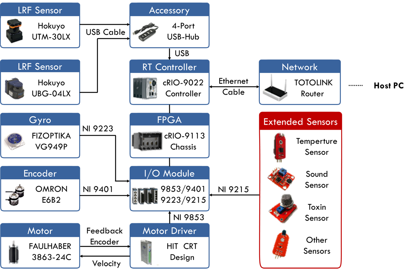
* HITCRT is short for Harbin Institute of Technology Competitive Robot Team
The Challenge
Robot Localization: One fundamental problem that the robot has to solve if it’s going to map the environment is essentially figuring out where it is within the environment. This gets a little challenging because we want the robot to explore the unknown environment, so there is no global coordinate system. The coordinate system should be defined based on the robot, where it is and what it’s looking at.
Mapping the Environment: The second challenge is about how to build a map of the environment quickly and effectively with limited sensors. And that map should consist of features like doorways, ceilings, windows, walls, people, furniture and etc. The robot can be commanded remotely, but it will be more challenging to let the robot figure out where to go on its own and build the map autonomously.
Software Design: Since E-Builder robot has many applications and requirements always keep changing during the development, the third challenge lies in how to develop scalable, modular, reusable, extensible but simple applications with LabVIEW. In other words, our application should be software level reconfigurable.
The Solution
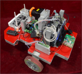
Design & Make Robot: So before talking about how E-Builder works, let me briefly introduce how we design and make the whole robot. We actually start from scratch. To test our crazy idea, we designed a small prototype vehicle in Solidworks to test the feasibility first. Then we kept modifying the vehicle model until we believe it can meet all the requirements. With this prototype, we decided to take the next big step, to develop a real robot. Obviously it’s impossible for us students to buy the expensive instruments and sensors that we integrated into the 3D model, so we persuaded the relevant labs to lend these equipments to us. Then we bought all the other necessary material from local market, cut the aluminum square tubes, welded the body parts, assembled the robot and finally, it’s done.
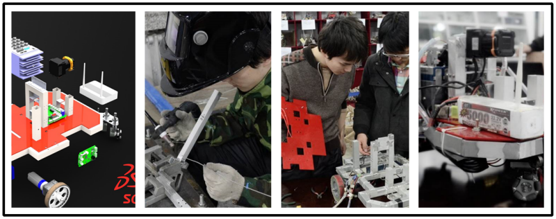 Figure 1: From Solidworks Prototype to Real Robot
So how does it work? Well, let me try to explain it, make it simplified. Generally we have three steps, Perception, Computation and User Interfaces. Let’s start form perception step, see Figure 2.
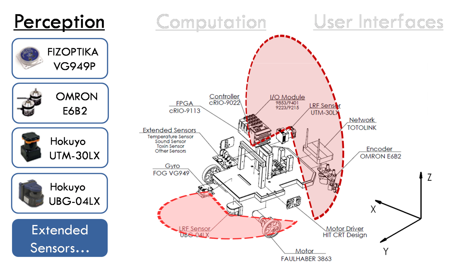 Figure 2: Perception Step
Perception Step
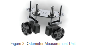
Positioning Mechanism: Now obviously if the robot is going to map the environment, it should figure out where it is within the environment first. For that, we use an analog FOG(fiber optic gyroscope) to sense changes in orientation and measure the posture of the robot. We fuse the posture information with an odometer measurement unit to get an estimate of the location of the robot. Here, the odometer measurement unit is specially designed (see Figure 3).
We use two incremental rotary encoders to capture the moving of two orthogonal arranged Omni-wheels to record changes in position. The orthogonal arranged Omni-wheels ensure that both forward and lateral move could be recorded. This approach can also reduce the deviation caused by misalignment of two differential wheels.
Environmental Perception: The robot also need to perceive the environment and gather information for mapping, we use two laser range finders to achieve this. One laser range finder, Hokuyo UBG-04LX is used to scan the environment to detect obstacles approaching from the front, and any obstacles that run into the robot’s way. The other Laser range finder, Hokuyo UTM-30LX is used to scan the environment vertically. So basically we can use this laser range finder to get the sections (in XZ plane) of the environment while robot is moving, and there is no doubt that these sections can be interpreted into a 3D map if combined with robot position information.
cRIO Setup: So all the vast amount of information is then fed into our cRIO. We use NI 9401 ultrahigh-speed digital I/O to measure the two incremental encoders and use NI 9223 16-bit simultaneous analog input module to measure signals provided by analog gyroscope. Since the robot needs to equip various extended sensors to meet different task requirements, we use NI 9215 4-channel, 16-bit, ±10 V Analog Input Module to deal with these sensors. We also use NI 9853 high-speed CAN module to communicate with two motor drivers to control the motion of two differential wheels. All these information acquired by NI C Series I/O module is then passed to cRIO-9113 FPGA chassis. To acquire the data of two LIDARs, we extend the USB port provided by cRIO-9022 Real-Time Controller with a 4-port USB hub first and then plug LIDARs to this hub. This allows the Real-Time Controller to access two LIDARs independently. With all the information ready, it comes to the second step, computation, see Figure 4.
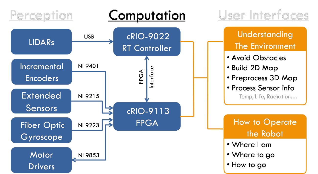
Figure 4: Computation Step
Computation Step
Localization in FPGA: Since NI cRIO-9113 contains Xilinx Virtex-5 reconfigurable I/O (RIO) FPGA core for ultimate processing power, we use the FPGA as a co-processor to help the robot to figure out where it is within the environment. The FPGA will compute the robot pose using information provided by incremental encoders and gyroscope every 5us, the whole procedure is outlined in Figure 5. You can view our program source code for more details about self localization using FPGA.
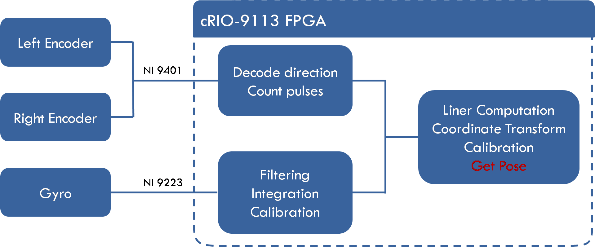 Figure 5: Self Localization Using FPGA
Software Architecture in cRIO: Now that the robot knows where it is within the environment, it still needs to have an understanding of the environment and figure out where to go, how to go if it’s to be autonomous, and the cRIO-9022 Real-Time Controller will help to fulfill that. So before I talk about how the real-time controller works, let me briefly tell something about the software architecture in cRIO, see Figure 6.
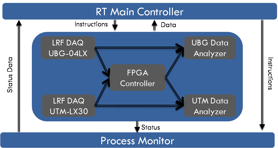 Figure 6: RT Software Architecture
Actors Setup: We use the Actor Framework as the basis for an embedded control solution. Each actor is by nature a while loop, so you can see from Fig 5 that we have 7 independent tasks running in cRIO RT. We have a RT Main Controller actor manages all other actors. This actor is also responsible for sharing data with and receives instructions from a user interface running on a host computer. We have a Process Monitor actor gathers execution status from other actors, the execution status can be used to debug the RT application. We actually created only one actor for acquiring LIDAR data but launch this actor twice to acquire data from UBG-04LX and UTM-LX30 independently. Since FPGA Controller manages FPGA Interface, RT can communicate with FPGA through this actor. Each LRF DAQ actor has an analyzer actor to form a Producer/Consumer pattern.
Tasks Setup: So with all these actors collaborating with each other, the real-time controller can do a lot of job. For example, with information provided by UBG-04LX DAQ actor, the UBG Data Analyzer actor can identify obstacles and gaps, or open areas in the robot environment and tell FPGA Controller actor to implement reactionary motion using VFH(Vector Field Histogram) method. Since line segment is the most widely used feature to construct geometric primitive based map, the UBG Data Analyzer actor also extract line features out from Hokuyo UBG-04LX LIDAR data, and combine this with robot pose information(provided by FPGA Controller actor) to build a 2-Dimensional polygonal map that consists of only line segments. Another reason of only using line segments lies in the fact that it is easy to manipulate and can be used directly for localization and path planning. (Because the robot already has a self localization system, using the 2D map for localization and path planning is not included in the current project) In our project, the robot updates its 2D map 10 times a second.
Unlike building a 2D map, the real-time controller does not build the 3D map directly. It just synchronizes UTM-LX30 LIDAR data with robot pose information to get the sections (in XZ plane) of the environment while robot is moving. These sections will be sent back to a host PC to reconstruct the 3D environment. Notice that the UTM-LX30 LIDAR can scan the environment 40 times a second (it turns out 20 times a second is enough in our project), so the host PC can receive enough sections to build a 3D map that consists of features like doorways, ceilings, windows, walls, people, furniture and etc. The map building (2D&3D) results will be covered later in User Interface sections.
Network Communication: So how do we send these computation results as well as the vast amount of sensor information back to a host PC and how does the robot receive instructions from a host PC? We base the network interface on the Linked Network Actor. By adding a linked network actor to our host and remote applications, we create two network streams, one each direction, that allow the applications to exchange message objects. In our project, we implement one particularly elegant way to minimize the coupling between application instances. We have created an actor, called Communication Interface, that has a nested Linked Network Actor. Communication Interface provides a set of methods and messages that defines the complete interface between cRIO RT and host PC, but does not contain any target-specific code. When a Communication Interface receives a message, it forwards a copy of the message across the network to its remote counterpart.
We have created two children of this actor, one for the host and one for the RT target. Each child provides an override method for each message it expects to receive from a remote Communication Interface. These overrides contain target-specific code.
- The RT child, RT Main Controller, overrides these methods to forward the computation results and sensor information to the host PC.
- The host child, Network Controller, overrides these methods to give instructions to the RT target.
The host and RT target only share Linked Network Actor and Communication Interface, and neither of these actors link to platform-specific code. See Figure 7 for host PC network diagram and Fig 8 for cRIO RT network diagram.
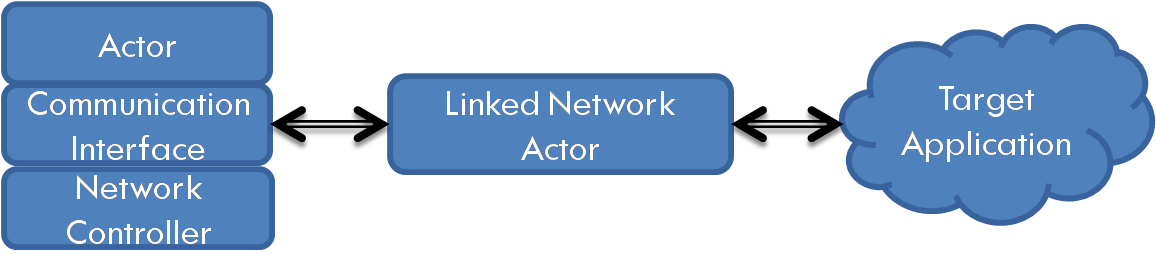
Figure 7: Host PC Network Diagram
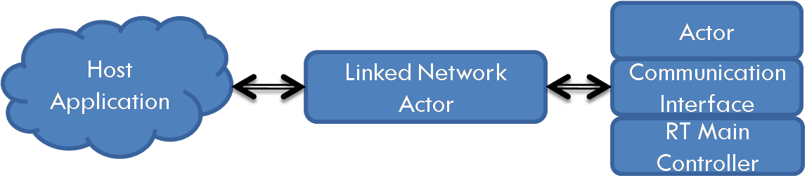
Figure 8: cRIO RT Network Diagram
User Interfaces Step
The last problem is how do we convey this information provided by a robot to a person? So for this, we developed many different types of user interfaces and this comes to our third step, User Interface, see Figure 9.
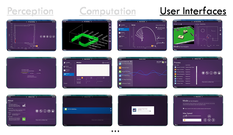 Figure 9: User Interface Step
So starting from a two-dimensional map building UI, a starting menu, a UI that monitors sensors, a simulation environment, … , even a dialog that asks whether or not to exit the system. But here I’m going to talk about only two types of these user interfaces and the rest is left to you to explore. Now the first type of user interface is related with simulation. As is known to all, simulation is critical for robot development, it allows developers to validate their design and algorithm more efficiently and effectively. We create the 2D&3D map building simulator UI to view and interact with simulated robots to test our map building algorithms, see Figure 10.
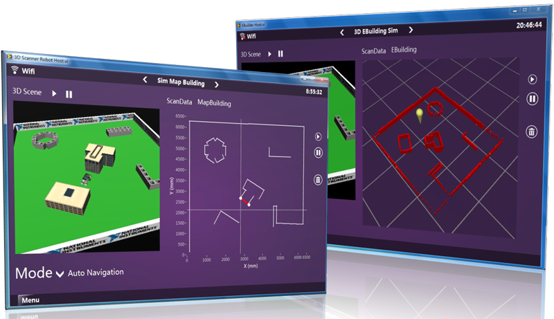 Figure 10: 2D&3D Map Building Simulator
When we have validated the map building algorithms, what we need to do next is just applying these algorithms to the real robot and it just works! So the second type of user interface is about displaying the map built by our real robot, see Figure 11~ Figure14.
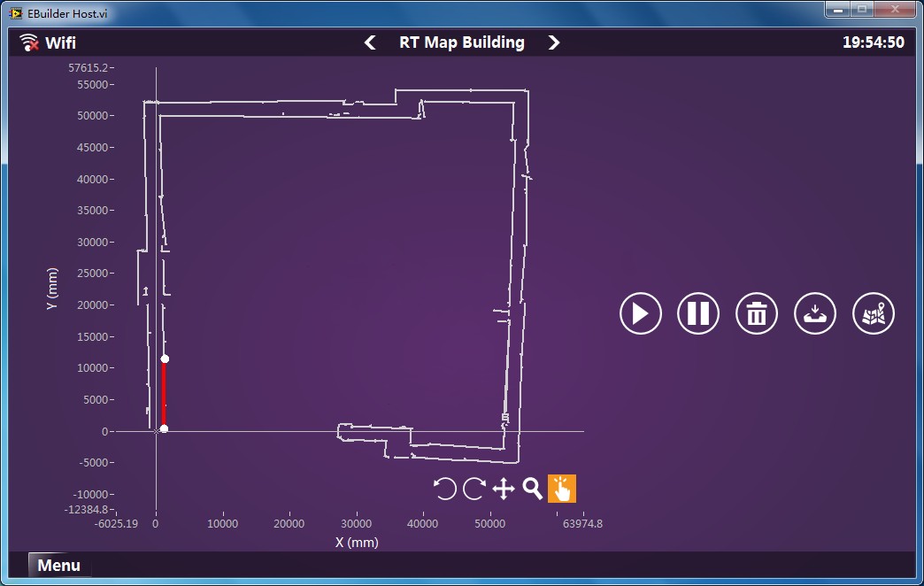
Figure 11: 2D Map of a 180m+ Corridor
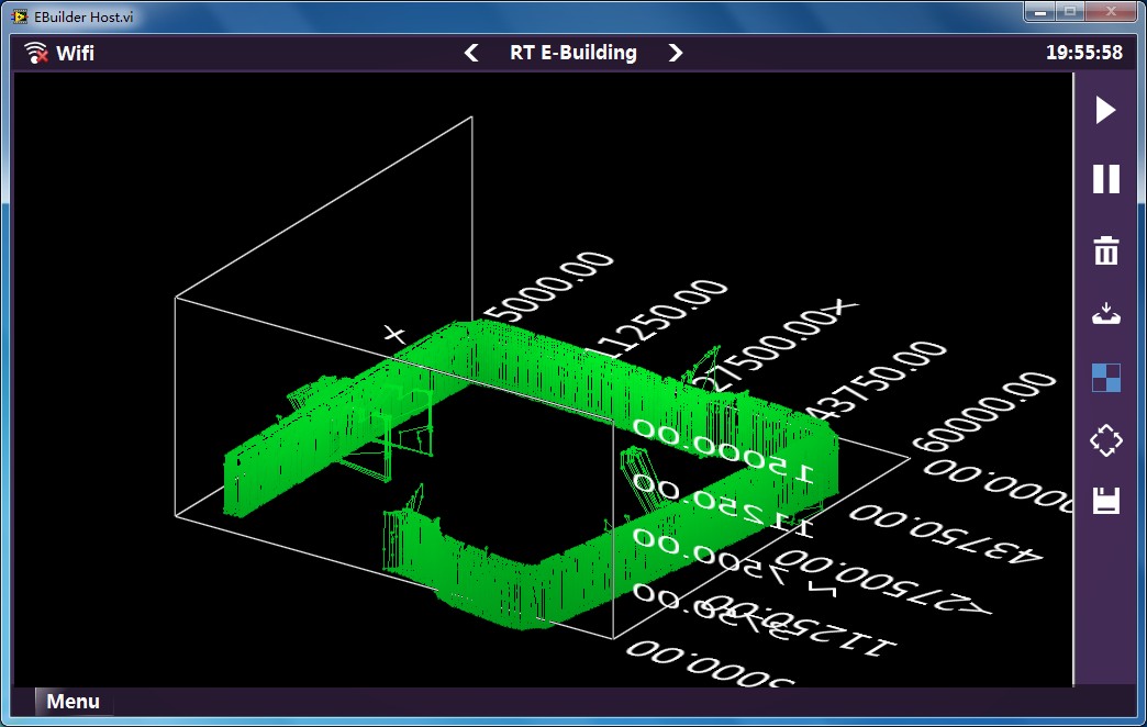
Figure 12:Raw Corridor Section data
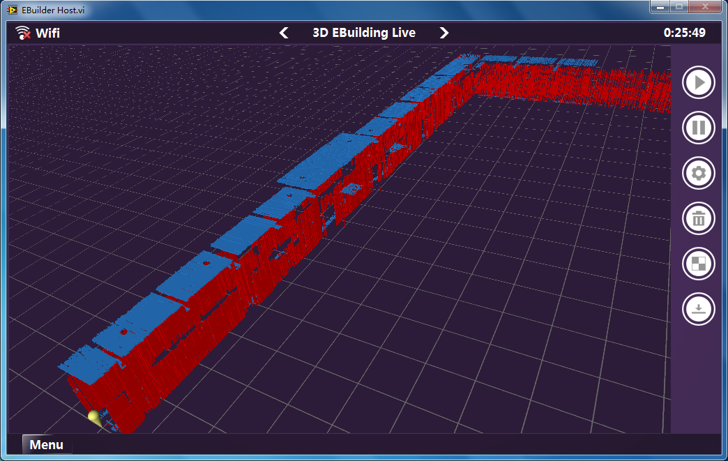
Figure 13: Reconstruct the Corridor Using 3D Occupancy Grid Method
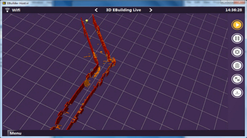
Figure 14: Another example of 3D Map Building Using 3D Occupancy Grid Method
Figure 11 shows a 2D map of a 180m+ corridor, the map consists of only line segments and it takes the robot about 7 minutes to build the whole map. While building the 2D map, the robot also keeps gathering corridor sections. The robot can store these sections in cRIO first and then transfer these data files back to a host PC (through FTP) to rebuild a 3D map, we call this type of 3D map building Offline 3D Map Building. We also have Online 3D Map Building, the robot just transfer each section back to a host PC when section data becomes available, and the host PC can build a 3D map using each of these sections incrementally. Figure 12 shows a rough 3D estimate of the same 180m+ corridor using corridor sections. Figure 13 shows that we reconstruct the corridor using 3D occupancy grid method and you can clearly see doorways, ceilings, windows and walls from this 3D map. Figure 14 shows another example of 3D map building using 3D occupancy grid method, this time the robot just ignores ceilings so that you can see the interior structure directly.
Software Architecture in PC: We base our host PC software architecture on the Actor Framework too. We have done quite a bit of work to design an architecture that can enable a highly modular application that enables multiple people to work on separate components without impacting or breaking un-related components. Figure 15 shows our staring up UI. You can see the modularity is made possible by the fact that several dependencies are dynamically loaded at run-time, including the plug-ins and the animations. In addition, the menu interface was designed separate of this application and is another independent resource.
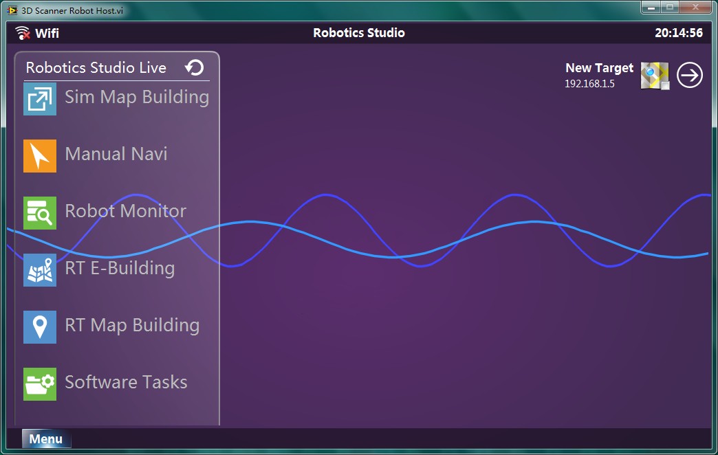
Figure 15:Starting Up UI

Figure 16_Host PC Software Architecture
Fig 16 illustrates how our host PC application works. There are actually two types of actors in the host PC application, the system level actor and the plug-in level actor. The system level actor Plug-in Controller will use a factory pattern to dynamically load and run all the plug-in actors. Other system level actors will provide various kinds of support to these plug-ins. We use subpanels to display plug-in UI in the top vi. So you can see our host PC application is software level reconfigurable. By designing different types of plug-ins and upgrade the RT application (if necessary), we can let our robot have different kinds of applications. Since we have provided a lot of system level actors, to design a new plug-in is very easy. The plug-in just needs to focus on the task itself and leave other things such as UI effect, sound effect, notification, network operation to the system actors.
Benefit of using LabVIEW and NI tools
- NI CompactRIO combines an open embedded architecture with small size, extreme ruggedness, hot-swappable industrial I/O modules, and is powered by the NI LabVIEW reconfigurable I/O (RIO) architecture. The needs for our robot system are diverse, such as acquiring raw sensors data for robot localization, controlling motor drivers, especially the various expended sensors for rescue and exploration. NI's differentiated expansion I/O offering provides a complete range of products to meet these needs. The reconfigurable I/O FPGA chassis let our robot reconfigurable too.
- The Actor Framework is a template for creating LabVIEW applications that consist of multiple, independent tasks that need to communicate with each other. Because actors are LabVIEW classes, actors are far more reusable and scalable than traditional queued message handlers. We take full advantages of these features, making the code high cohesion and low coupling. When adding a new module to the project, this ensures us greatly minimizing the impact on the overall codes and makes our codes easy to maintain and extend.
- Every autonomous or semi-autonomous robot, in some form or another, must sense it's environment, make a decision, and act on the environment. The LabVIEW Robotics module provides APIs and example programs for each step of the sense - think - act process. By providing a single environment that is a framework for combining graphical and textual code, LabVIEW gives us a really convenient platform to test and analysis our mapping algorithm. Furthermore, with new libraries for autonomy and an entirely new suite of robotics-specific sensor and actuator drivers, the tested algorithms in simulation could be directly used in our robot and creating maps in real scene. These ensure us to complete the whole project within only three months.
Project Video
http://youtu.be/g8fiGNaImHw (For United States)
http://www.dailymotion.com/video/x109r5b_ebuilder-robot-by-hitcrt_tech (For Europe)
http://v.youku.com/v_show/id_XNTYyMTMxOTA0.html (For China)
Level of Completion fully functional
Time to Build 3 months
Robot Parameter
Overall Size: 50cm X 45cm X30cm
Weight: 8.5kg (battery not included)
Cruise Duration: more than 1hour
Remote Control Distance: less than 100m
Max Speed: 0.45m/s
Range of Application:
- 2D Map Building works better in structured environment
- 3D Map Building suits both structured and unstructured environment
* 6C 5000mAh lithium battery is used to test the Cruise Duration;
* Remote Control Distance depends on the router and the complexity of environment;
* You can change the motors to increase Max Speed;
* Power consumption depends on the tasks.
Notice
* Please make sure you have installed the following software modules and toolkit before running our project code.
LabVIEW 2012
LabVIEW FPGA Module 2012
LabVIEW Real-Time Module 2012
LabVIEW Robotics Module 2012
* Please unzip the project code in the root directory of your hard-disk.
* Please open the vi through lvproj. Make sure you have read the user manuals before operating the application.
-
2013 LabVIEW Student Design Projects
-
All Student Design Projects
-
Application Architectures and Development
-
CompactRIO Materials
-
controls
-
LabVIEW
-
NI CompactRIO
-
NI cRIO Controller
-
Robot Projects
-
Robotics & Mechatronics Systems
-
Sensor and Other Drivers
-
Single-Board RIO
-
Tecnova Electronic Engineering - Case Studies
-
Tecnova Services and Solutions - Case Studies
-
サービスロボット
-
教育ロボット
-
産業ロボット
- Mark as Read
- Mark as New
- Bookmark
- Permalink
- Report to a Moderator
well done friends
good concept. also i must mention that the quality of user interface is stunning . please upload your project report if any, so that other users can read and understand your project in a better way.
Freelance LabVIEW and Arduino programmer.
For projects contact me ; djac791@gmail.com
- Mark as Read
- Mark as New
- Bookmark
- Permalink
- Report to a Moderator
Unbelievable!! You guys are the most brillant ones I have ever saw!!! Go!!! HIT-CRT!!!
- Mark as Read
- Mark as New
- Bookmark
- Permalink
- Report to a Moderator
非常有创意,支持!!
- Mark as Read
- Mark as New
- Bookmark
- Permalink
- Report to a Moderator
nice job
- Mark as Read
- Mark as New
- Bookmark
- Permalink
- Report to a Moderator
Really impressive, you guys are great, enjoy your robotic develop journey.
- Mark as Read
- Mark as New
- Bookmark
- Permalink
- Report to a Moderator
does the vi's execute without having the required hardware?
Freelance LabVIEW and Arduino programmer.
For projects contact me ; djac791@gmail.com
- Mark as Read
- Mark as New
- Bookmark
- Permalink
- Report to a Moderator
Hi, you can run host PC application without the required hardware, it's just user interface.
- Mark as Read
- Mark as New
- Bookmark
- Permalink
- Report to a Moderator
good
- Mark as Read
- Mark as New
- Bookmark
- Permalink
- Report to a Moderator
Although I don't understand ,it feels sharply
- Mark as Read
- Mark as New
- Bookmark
- Permalink
- Report to a Moderator
perfect~~~
- Mark as Read
- Mark as New
- Bookmark
- Permalink
- Report to a Moderator
good
- Mark as Read
- Mark as New
- Bookmark
- Permalink
- Report to a Moderator
非常好,支持
- Mark as Read
- Mark as New
- Bookmark
- Permalink
- Report to a Moderator
well done! A nice job
- Mark as Read
- Mark as New
- Bookmark
- Permalink
- Report to a Moderator
这个不是第二届全国高校虚拟仪器大赛的冠军作品吗?
- Mark as Read
- Mark as New
- Bookmark
- Permalink
- Report to a Moderator
Dear sir/madam! i am adnan jafar from pakistan studying electronics engineering from islamia university bahawalpur.. i am very excited and impressed to see you work in this project.. i will never forget you guys.. you are realy a genius guy.. dear can you send me the roport of this project on my email engr.adnan13@yahoo.com.. i will be very thankful to you if you guide me in proceeding with this project
