From 04:00 PM CDT – 08:00 PM CDT (09:00 PM UTC – 01:00 AM UTC) Tuesday, April 16, ni.com will undergo system upgrades that may result in temporary service interruption.
We appreciate your patience as we improve our online experience.
From 04:00 PM CDT – 08:00 PM CDT (09:00 PM UTC – 01:00 AM UTC) Tuesday, April 16, ni.com will undergo system upgrades that may result in temporary service interruption.
We appreciate your patience as we improve our online experience.
Contact Information
University: University of Southampton
Team Members (with year of graduation): Qasim Al-Mansoor (2015); Matthew Marinaccio (2015); Jack White (2015);
Project Supervisor: Dr.Mohamed Torbati, Professor Suleiman Sharkh, Dr.John Atkinson, Professor David Thompson.
Email Address:qham1g11@soton.ac.uk, mm22g11@soton.ac.uk, jaw1g11@soton.ac.uk
Project Information
Title:
Design and Manufacture of a Miniature Railway Locomotive
Description:
The purpose of the project is to design, build and test a remotely controlled 10.25” gauge locomotive with an energy recovery system to recover kinetic energy otherwise lost during braking. The locomotive design must adhere to the rules and technical specification of the 2015 IMechE Railway Challenge which requires complete remote control of the all the locomotive functions. Other factors to be considered include: cost, ergonomics, maintainability, manufacturability and reliability.More information can be found in the attached report.
UPDATE: University of Southampton's Successes in the 2015 IMechE Railway Challenge
Products:
Hardware
Software
The Challenge:
The overall aim of this project was to design and manufacture a miniature railway locomotive for entry into the IMechE Railway Challenge competition in June 2015. In doing so, the locomotive would have to be designed to adhere to a number of challenging technical specifications as set by the IMechE. The locomotive has been manufactured using aluminium frame and incorporates two bogies, each with two chain-driven wheelsets. A failsafe vacuum brake system has been implemented along with two DC Lynch motors in a monomotor arrangement. A supercapacitor has been used to store recovered braking energy and primary power is provided by a petrol generator. An aluminium plate shell will provide weatherproofing for the system whilst the myRIO microcontroller provides the means to control the entire system via a Wi-Fi linked tablet. The electronics and control team had the responsibility of designing and building the software and hardware required to control and monitor the following subsystems on the locomotive:
Sensor Systems
Braking System
Control vacuum system operation.
Traction System
Control the speed and direction of motors’ rotation
Power Circuit
Controls the amount of power between the generator and traction system
Battery system for ancillary components
System selection, voltage and State of Charge (SOC) monitoring.
The Solution:
With so many systems to control, the electronics and control team decided to tackle each subsystem individually. This allowed the testing and troubleshooting before combining the systems together.Whilst other subteams were finalising their designs, the inputs and outputs for the various functions were planned out to allow for constant moniroting of the design and control implementation process. The diagram below shows the final systems diagram:
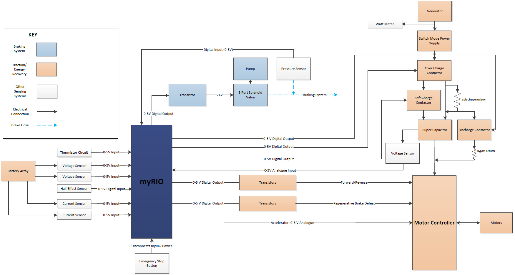 Figure 1: Full systems diagram showing the inputs and outputs from the myRIO
Speed Measurement
To measure the speed of the locomotive, an NPN Hall effect sensor mounted on a 3D printed L-shaped bracket was used. A magnet was placed in cylindrical on the locomotive axle as shown below:
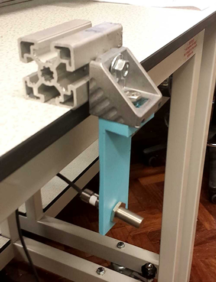
Figure 2: Hall effect sensor mounting
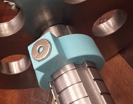
Figure 3: Magnet bracket placed on axle
To calculate the speed of the locomotive, a VI was set up with a count up function. A pulse is created every time the magnet on the axle is aligned with the sensor. The VI calculates the time between consecutive pulses and converts it into a frequency. The frequency is then converted into an RPM value and speed depending on the axle circumference.
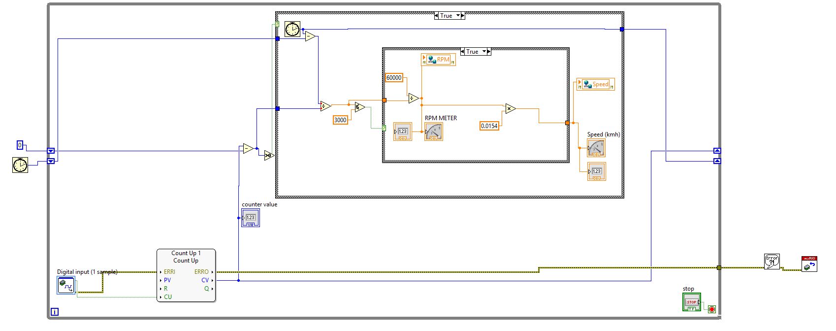
Figure 4: LabVIEW VI for speed measurement
Fire Detection
The technical specification of the competition requires the employment of a fire detection system that uses heat detection. Once activated, the system shall give an indicator to the driver and activate the brakes.
Because of their suitability for the application, a fixed heat detector concept was used. A 1k Ω thermistor was connected in series with a 1k Ω resistor. A VI was created to measure the voltage across the thermistor and calculate its resistance. Using the stein-hart hart equation, the thermistor’s resistance is used to calculate the temperature of the locomotive. A threshold temperature is set so that when the measured temperature exceeds the threshold temperature, a digital signal is sent to the brakes channel to activate them. The same signal is alo used to activate a pop-up box to indicate to the driver that there is fire in the locomotive.
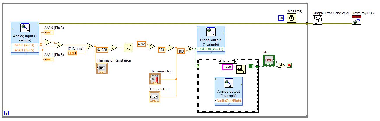
Figure 5: Fire detection VI
Motor Control
The control of the traction motors is provided by a motor controller (4QD-300). The unit takes a 0-5 V analogue throttle input which is translated into a corresponding terminal voltage which is proportional to a motor RPM. The unit has a regenerative braking mode which allows the motors to act as generators and charge the supercapacitors when a torque is applied to the motor shaft.
Brake Control
The braking system control occurs by way of manipulation of a solenoid valve. The solenoid valve is used to vary the pressure inside the system and so apply or disengage the brakes. This is done using a digital signal that when on, creates a vacuum inside a cylinder and when off pulls the vacuum to apply the brakes.
The motors and brakes control were combined and controlled depending on the output from the interface or tablet as follows:
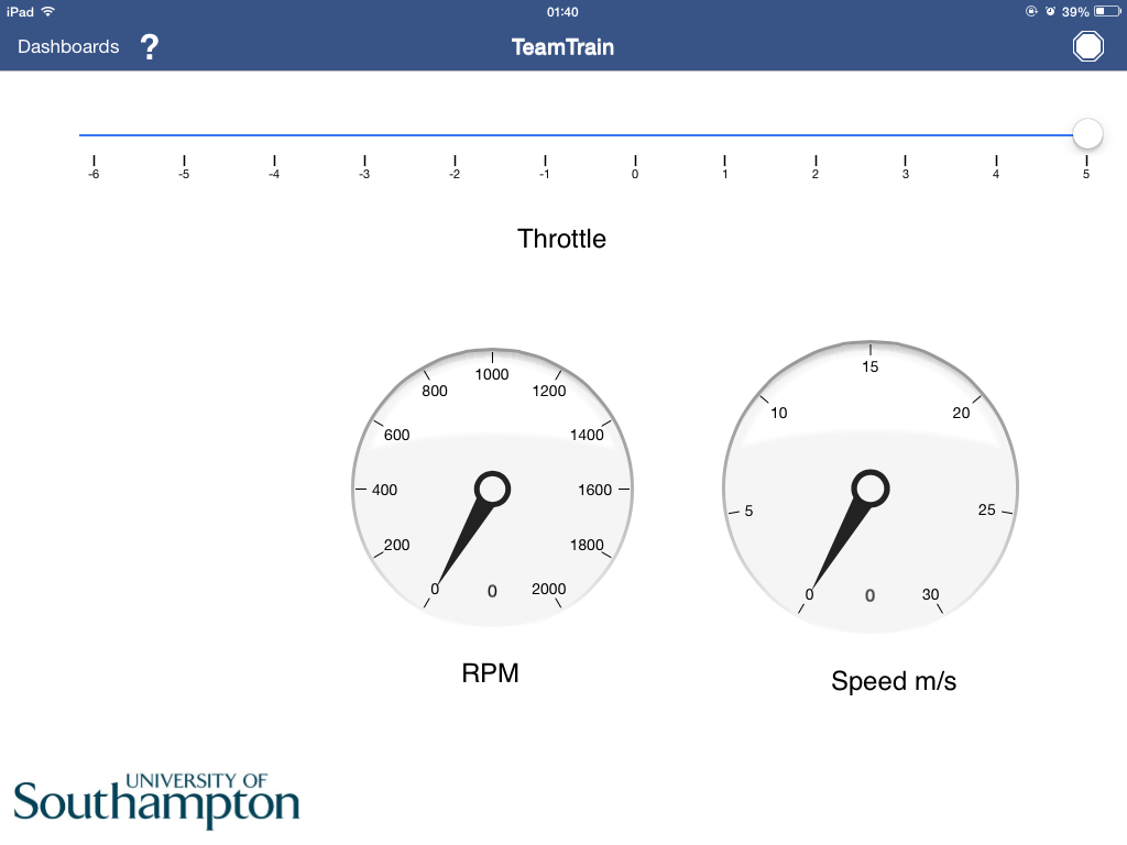
Figure 6: Motor control GUI
Power circuit
The Maxwell 48 V 165 F supercapacitor was selected as the storage medium for energy recovery due to its suitability as a low power density but high power source. During normal operation the supercapacitor is charged by the SMPS and provides a buffer for extra power when the 2.8 kW generator supply is insufficient for the driving power under high load, inclined conditions. The supercapacitor power circuit includes a 2.5 kW, 1 Ω soft charge resistor and a 2.5 kW, 2.2 Ω discharge resistor. The soft charge resistor is necessary to limit the current drawn by the supercapacitor during charging. This is because of the very low internal resistance of the supercapacitor which could lead to short circuit otherwise. The soft discharge resistor is required to control the discharge of the supercapacitor to drain the unit of any residual charge after use. It is also used as part of the overcharge protection circuit, keeping the supercapacitor voltage within operational limits. It also short circuits the supercapacitor when the locomotive is not in use. The soft charge by-pass switch is used to eliminate the losses associated from passing current through the resistor and switches to discharge and to avoid supercapacitor overcharge. All of the switches are automatically controlled by the myRIO depending on the supercapacitor voltage as follows:
• By-pass switch closes at 45 V
• Overcharge switch opens at 47 V
• Discharge switch closes below 1 V and above 46 V.
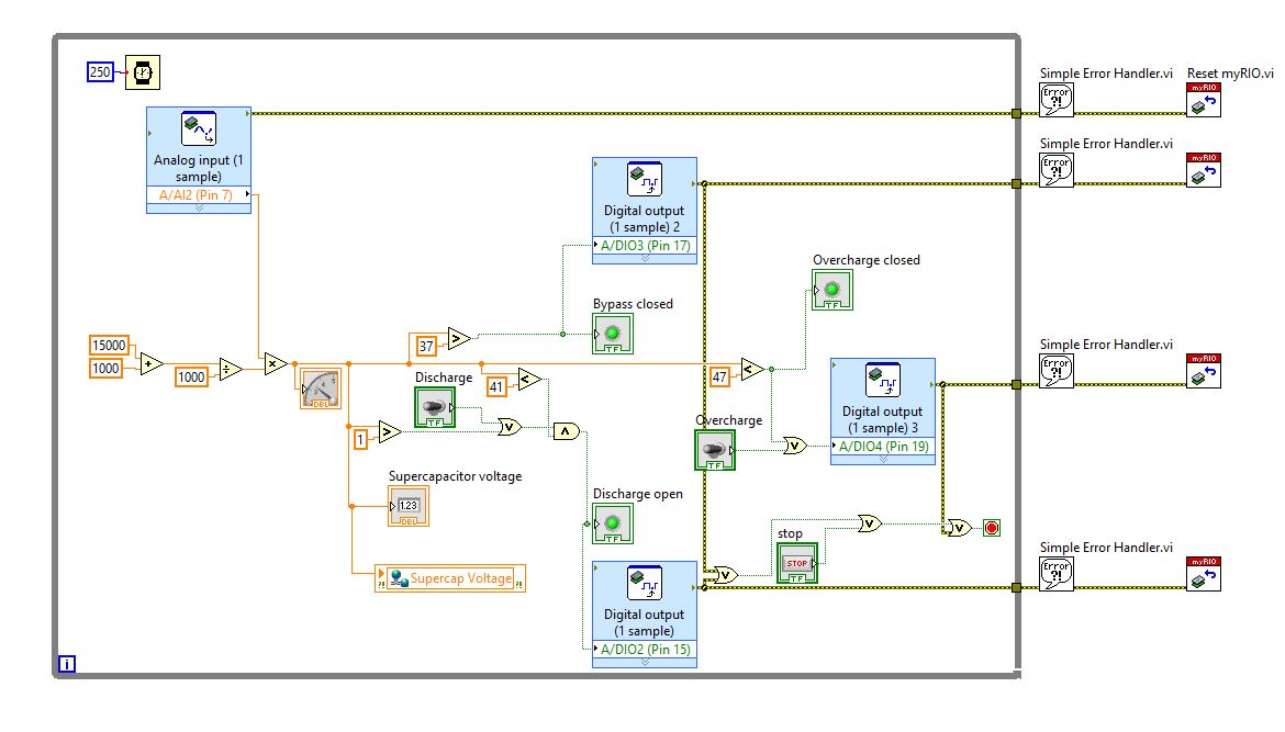
Figure 7: Power circuit VI
Ancillary battery system
As part of the electronics & control subsystem it was required to design a low voltage DC supply system for components such as the brake system solenoid, myRIO microcontroller and energy recovery circuit contactors. Two 12 V 55 Ah sealed, rechargeable lead acid batteries were selected as the ancillary power system. They are not charged on the locomotive but are easily accessible for replacement and batteries have been proven to last multiple days at a time. The selected ancillary power system is completely separate from the primary source such that in the event of a primary power circuit fault the myRIO is still powered and so functions safely. The voltage of the batteries is monitored so that the battery circuit is disconnected when the batteries voltage falls below a certain value. The monitoring of the current is done using Hall Effect current sensors.
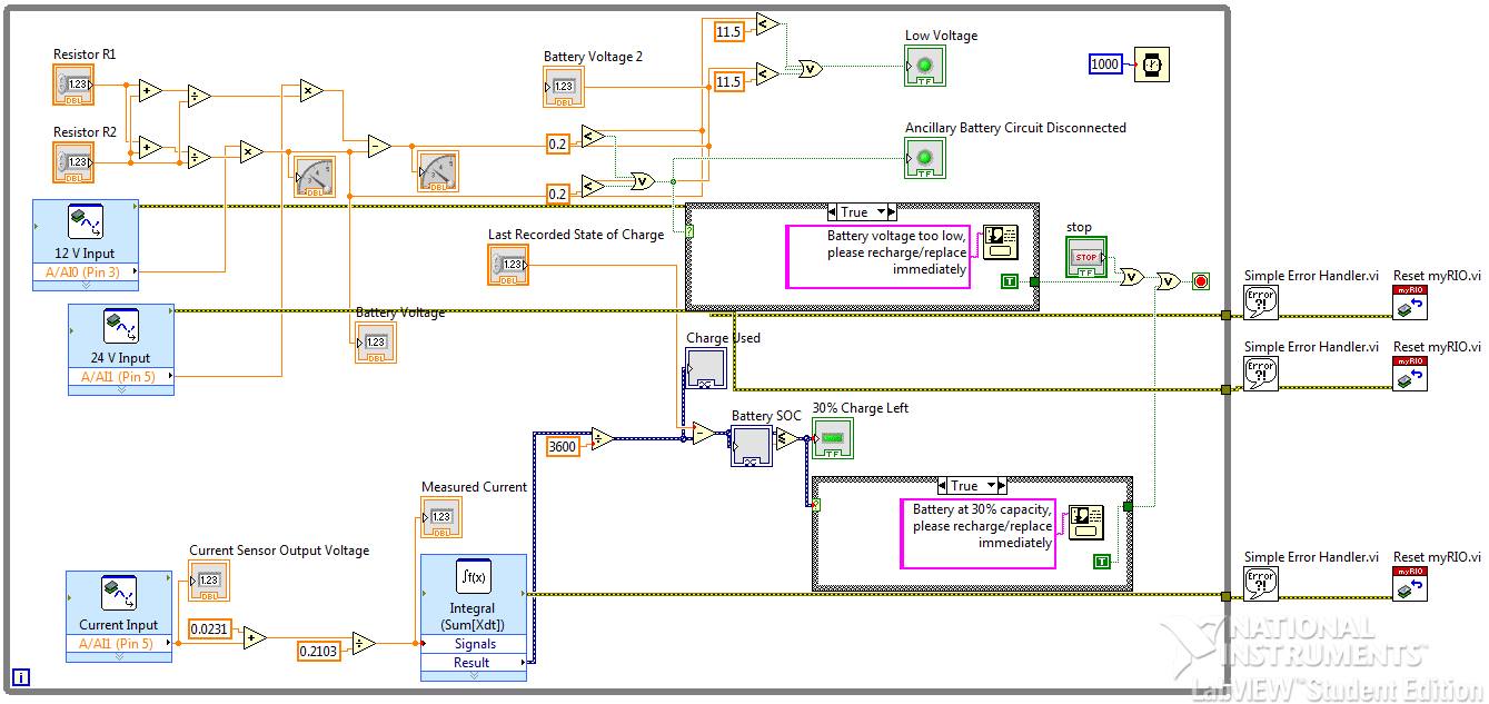
Figure 8: VI for monitoring the batteries voltage and SOC
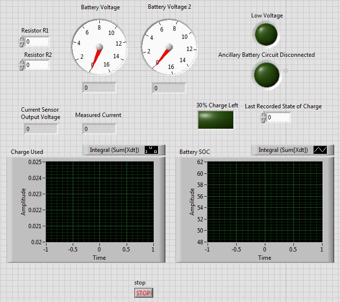
Figure 9: Front panel for battery voltage and SOC
The use of myRIO and LabVIEW has allowed flexibility and ease of programming for the project. At the beginning of the project, none of the team members had any experience with LabVIEW prior to the project. In a matter of weeks, the team was able to design and construct systems that are able of controlling a whole miniature locomotive. The graphical interface was very helpful for troubleshooting and creating quick test virtual instruments and proved to be very useful compared to scripted programming languages. With the importance of remote control in this project, the Wi-Fi hotspot feature and NI Data Dashboard application provide an easy and user friendly operator experience. Below is a screenshot of the preliminiary laptop GUI that was used during the first stages of testing:
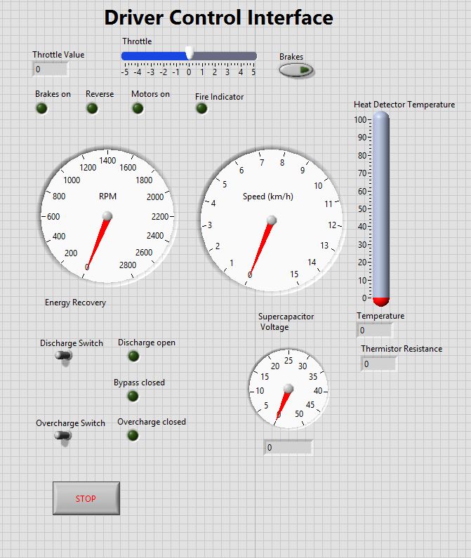
Figure 10: Driver GUI
Update to controls:
In preparation to the Railway Challenge and to achieve complete remote control without a laptop, the team decided to control the locomotive independently without having the need to connect the myRIO to a laptop and run the locomotive controls straight from the NI Data Dashboard application. All the previous VIs were set up as start up applications so that everytime the myRIO is rebooted the Vis are ran and all shared variables are deployed.
Update to Saftey measures
As part of the competition rules, it was required to deploy an emergency disconnect where in the case of Wi-Fi loss, braking is deployed. To achieve this, the TCP protocols tools were used. The TCP open function continuously searches for the tablet's IP address. In the case of communication loss,an error is sent to the control case structure and a signal is sent to the data dashboard application that immediately reduces the speed of the locomotive and applies the emergnecy brakes. A screenshot of the code is shown below (Many thanks to Charlotte Nicolaou from NI for her help with this problem):
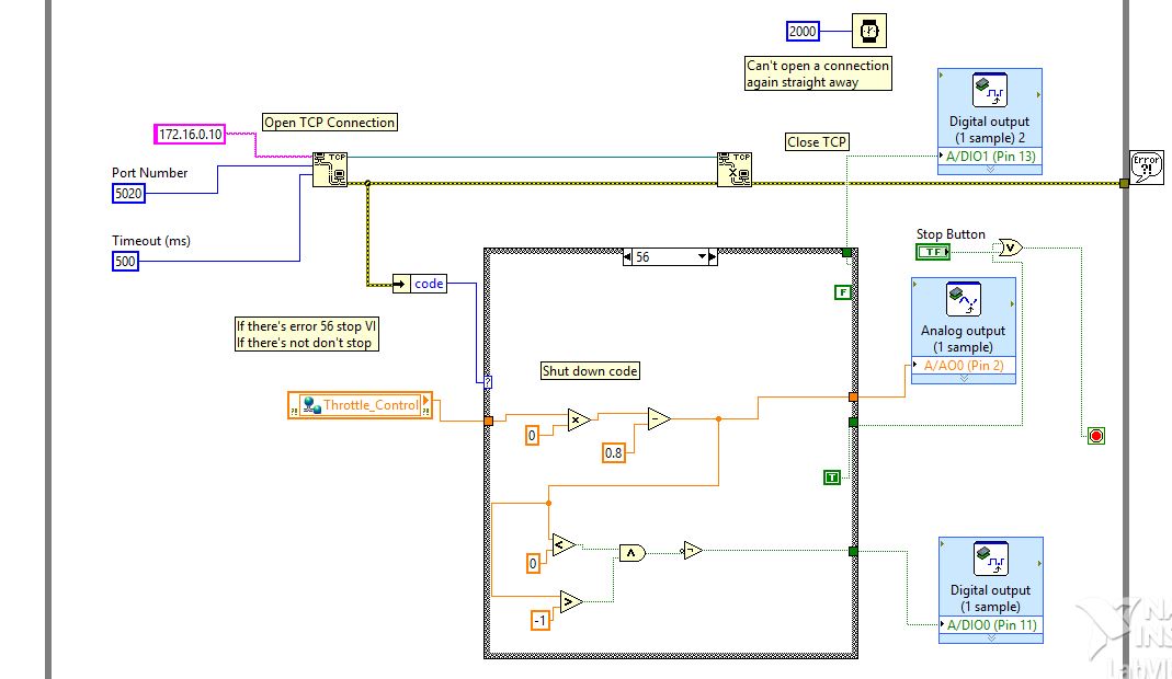
Figure 11: Emergency disconnect VI
Level of completion:
The team has been able to design and build a fully functional locomotive with opportunities for future developments. Although this has been the first year for such a project to run at Southampton University, the project will rerun for the next few years allowing the optimisation of the current manufactured locomotive. Further testing and refinement to the electronics systems is to be completed during June 2015 before the competition including the final refinement of the VIs and integrating them into one user interface for the operator.
Update on competition success:
The team has successfully competed in the 2015 IMechE Railway Challenge achieving third place overall and ranked top on all universities teams. All judges and spectators were impressed with the energy recovery system which controlled by the myRIO and LabVIEW has been able to set a new record for the energy recovery challenge.
Time to build:
The project has been ongoing from late September 2014 to early April 2015. It was developed alongside our final year studies and has required the equivalent of five months spread over the academic year. This includes preliminary research, component design and selection, LabVIEW programming of the myRIO, bench testing of subsystems, final assembly and testing and finally writing the project report.
Additional revisions:
As mentioned, 2015 was the first year the project was run at the University of Southampton. The project will run again in future years where the design of the current locomotive will be optimised and changed to adopt to any changes made to the competition rules.
Attach Poster
See the attachments for poster and the LabVIEW codes that were used during testing 'Bench-top testing' and the ones to be further refined for the railway challenge 'LabVIEW VIs'.
