- Document History
- Subscribe to RSS Feed
- Mark as New
- Mark as Read
- Bookmark
- Subscribe
- Printer Friendly Page
- Report to a Moderator
- Subscribe to RSS Feed
- Mark as New
- Mark as Read
- Bookmark
- Subscribe
- Printer Friendly Page
- Report to a Moderator
Cantilever Moment Instrument
Author(s):
Wong Ying Qian, Student
Wong Ka Pau, Student
Loo Wei Jie, Student
Rodney Tan, Senior Lecturer
Academic Institution:
Faculty of Engineering, Architecture and Built Environment
UCSI University, Malaysia
Products Used
NI USB-6008 DAQ
NI LabVIEW 8.5
The Challenge:
Cantilever, a beam supported only on one end, made the construction of overhanging structures without external bracing feasible. This is important as cantilevers are widely applied in structural construction such as bridges, towers, and aircraft. The development of cantilever moment instrument provides the platform for analysis to achieve a better understanding of the underlying principle of bending moment of a cantilevered beam.
The Solution:
LabVIEW 8.5 and NI USB-6008 DAQ are used to develop this instrument. The force applied and the distance from the root is acquired using NI USB-6008 DAQ. These acquired voltage values are shown in the graphical user interface developed using LabVIEW 8.5. The physical bending of the instrument is also shown in an animated graphics created.
Abstract
The development of Cantilever Moment Instrument is to measure the physics entity bending moment. The eventual aim is for the analysis of the effect of bending moment on a cantilevered beam, which is crucial in structural construction such as bridges, towers and aircrafts. Using the analog inputs of NI USB-6008 DAQ, the voltage changes due to the force applied and the distance of the force applied from the root are acquired. The acquired data are shown in the graphical user interface created using LabVIEW 8.5. The multiplication of force applied and distance result in bending moment, which is also shown in the graphical user interface. Based on this bending moment value, the animated graphics would show the physical bending of the hardware of the Cantilever Moment Instrument.
Introduction
Bending moment is defined as a force applied onto a beam multiplied by a distance between the force applied and the fixed-end root. Bending moment exists in a structural element when an external force is applied perpendicular to a beam. The beam would try to rotate either in clock wise or anti clock wise, depending the direction of the applied force, but for a beam with one end fixed, also known as cantilevered beam, the beam would tend to bend since it cannot rotate freely. The force is distributed along the beam as tensile and compressive stresses, which will concentrate at the root of the beam. If the beam is bent downward, the upper face of the beam will experience tensile stress while the bottom face of the beam will experience compressive stress. There exists a neutral face in between where it is neither compressed nor in tension.
The principle of bending moment is very important especially in the design of bridges, towers and aircrafts. A cantilever bridge is built using cantilevers, where the structures project horizontally into space, supported on only one end. Two projecting beams, one from each side respectively, are joined in the center by a connecting member and are supported on piers anchored by counterbalancing members. Some real world application examples are the Kentucky River Bridge, the Niagara Cantilever Bridge and the Poughkeepsie Bridge. However, the Fourth Railway Bridge in Scotland, which is a double cantilever railway bridge, remains as the largest breakthrough because it has the longest span in the world for seventeen years. Initially, it was designed as a suspension bridge but it had failed. Hence, it was reconstructed using the concept of cantilever, which is more stable.
System Overview
The complete system overview block diagram is as shown in Figure 1. The system consists of two sliding variable resistors, a computer with preinstalled LabVIEW 8.5 and NI USB-6008 DAQ.
The sliding variable resistors are each used to detect the force applied on the beam and to detect the distance between the force applied and the fixed-end root. The sliding variable resistor used to detect the force is placed directly under the beam, where the center of force is applied, in a vertical orientation. Thus when force is applied, the beam would bend downward and the slider will move downward together with the beam. This changes the voltage value which is directly acquired by the analog input of the NI USB-6008 DAQ. Using this voltage value, a formula derived based on experiments is used to calculate the force applied.
The sliding variable resistor used to detect the distance between the force applied and the fixed-end root is placed underneath the beam in a horizontal orientation. When the beam is moved, the distance changed. The variable resistor is also adjusted to trail the beam to measure the distance. The voltage value of this variable resistor is also directly acquired by the analog input of the NI USB-6008 DAQ. A calculation is done to obtain the distance based on the voltage value acquired. By multiplying the force applied and the distance, bending moment is acquired. The force, distance and the bending moment are shown in the graphical user interface developed using LabVIEW 8.5.
Minimal hardware is required because the NI USB-6008 DAQ is used to supply 5 V to the two sliding variable resistors and the voltage changes are obtained through the analog inputs of the NI USB-6008 DAQ. There are four assumptions that have to be made for this Cantilever Moment Instrument. First, the root of the beam fixed to the wall does not experience any deflection. Second, the beam at the wall is horizontal. Third, there is no bending moment at the free end of the cantilever and lastly, there is no shearing force acting at the free end of the beam. Also, the force applied is assumed to be concentrated loads instead of distributed loads which is not suitable to be applied in this Cantilever Moment Instrument.

Figure 1 Block Diagram of System Overview
Results and Discussion
The GUI of Cantilever Moment Instrument is created using LabVIEW 8.5. It is shown in Figure 2. The sliders are used to show the force applied and the distance of the force applied from its fixed-end root calculated from the formulas based on the voltage acquired through the analog inputs of NI USB-6008 DAQ. The digital values are also shown to the right of the sliders. The force is shown in unit gram while the distance is shown in unit centimeter. The multiplication of these two result in bending moment, which is in the unit of gram centimeter. It is shown in both the analog meter to the left of the sliders and the digital value is beneath the analog meter. The picture below the sliders is an animated graphic showing how distance of the beams changes based on the distance values and how the beam bends when force is applied. The bending is exactly the same with the bending seen in the hardware of the Cantilever Moment Instrument.

Figure 2 Graphic User Interface of Cantilever Moment Instrument
The LabVIEW software block diagram is shown in figure 3. It is made up of 33 blocks where 23 of them at the upper portion are used to acquire the voltage changes due to the force applied and the distance of the force applied from the fixed-end root, and another 10 blocks at the lower portion are used to generate the animated graphic.
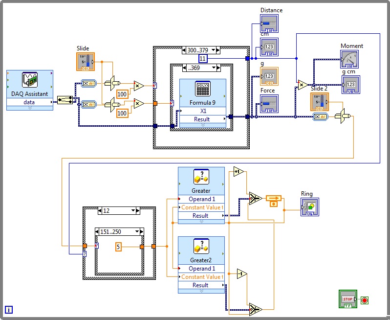
Figure 3 Software block diagram
From the GUI in figure 2, it can be seen that the distance of the Cantilever Moment Instrument is adjusted to 12 cm. The force applied is 200 g. Due to the tolerances in calculation, the force shown is 198 g. Thus, the bending moment is 2376 g cm. The graphic below the force slider shows the bending of the Cantilever Moment Instrument Hardware. The experimental setup is shown in figure 4 below. The overall setup is on the left of figure 4 while a zoom-in to the hardware of Cantilever Moment Instrument is on the right of figure 4.
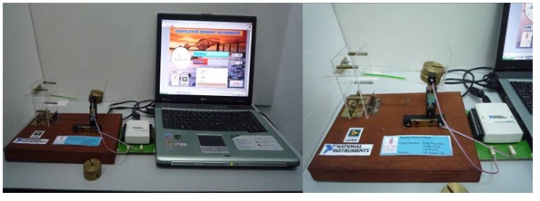
Figure 4 Experiment Setup of Cantilever moment instrument
Experiments were repeated a few times using different value of distance and different value of force. The results are tabulated in table I. From the table, it can de deduced that for the same value of distance, the moment increased when force applied is increased. When the value of distance is reduced, for the same value of force applied, the moment is reduced. Thus, moment is increased when the force applied is increased for the same distance while moment is lower when the distance of the force applied from its fixed-end root is reduced. Furthermore, for the same distance, when the load is increased, the force detected becomes less accurate compared with the actual force applied. This is due to the center of mass where it is not concentrated at the center anymore as the 100 g loads are stacked on top of another as shown in figure 3.
Table I Results
Distance (cm) | Force applied(g) | Calculated force in LabVIEW(g) | Moment (g cm) | Calculated moment in LabVIEW(g) |
12 | 100 | 103 | 1200 | 1236 |
200 | 203 | 2400 | 2436 | |
300 | 296 | 3600 | 3552 | |
400 | 382 | 4800 | 4584 | |
11 | 100 | 108 | 1100 | 1188 |
200 | 212 | 2200 | 2332 | |
300 | 317 | 3300 | 3487 | |
400 | 397 | 4400 | 4367 | |
10 | 100 | 119 | 1000 | 1190 |
200 | 215 | 2000 | 2150 | |
300 | 333 | 3000 | 3330 | |
400 | 398 | 4000 | 3980 |
Conclusion:
By integrating LabVIEW 8.5 and NI USB-6008 DAQ, Cantilever Moment Instrument has successfully demonstrated the idea of developing a feasible and valid instrument for analyzing cantilever bending moment. This Cantilever Moment Instrument is beneficial for stress analysis, structural construction design and academic research.
For more information, contact:
Rodney Tan
Senior Lecturer
University College Sedaya International (UCSI), Malaysia
No:1, Jalan Menara Gading, UCSI Heights, 56000 Kuala Lumpur Malaysia
Tel: +6017-3078955
Fax: +603-91023606
Email: rodneyt@ucsi.edu.my
