- Document History
- Subscribe to RSS Feed
- Mark as New
- Mark as Read
- Bookmark
- Subscribe
- Printer Friendly Page
- Report to a Moderator
- Subscribe to RSS Feed
- Mark as New
- Mark as Read
- Bookmark
- Subscribe
- Printer Friendly Page
- Report to a Moderator
Contact Information
University:
- Adamson University (Manila, Philippines)
Team Members (with year of graduation):
- Cherie Dy J. Arao (2013)
- Perdi L. Barbadillo (2013)
- Nelson G. Biscocho Jr. (2013)
- Krizzel M. Silapan (2013)
- Ardinne E. Sugian (2013)
Faculty Advisers:
- Engr. Albert D.C. Evangelista
- Evelyn Q. Raguindin, PECE
Email Address:
Submission Language:
- English
Project Information
Title: Adamson University’s Sewage Treatment Plant Real-Time Monitoring of pH and Water Level and Automation of Chlorine Control Using National Instruments’ CompactRIO and LabVIEW
Description:
This study developed a monitoring system for the Equalization and Clean Water tanks of Adamson University’s Sewage Treatment Plant (STP). The system acquires the pH and water level for each tank. Chlorine is released in the Clean Water tank provided the solution is ready and is done for further treatment of water to be stored and released in toilets. Results are analyzed and interpreted at the base station. Database was created for data logging.
Products
- NI PS-15 Power Supply
- NI cRIO 9073
- NI 9474
- NI 9203
- LabVIEW 2009
- LabVIEW Real-Time Module 2009
- SDX Pressure Sensor 0-35 ft. range
- SDX Pressure Sensor 0-5 ft. range
- Lutron TR-PHT1A4
- TowerPro 98055BB
The Challenge
To design a system for Adamson University's Sewage Treatment Plant for automation of chlorine control and for real-time monitoring of pH and water level for Equalization and Clean Water tanks.
To acquire the measurements of pH and water level through the pH sensor and Water level sensor respectively, with its signals to be transmitted to computer, and to analyze and interpret the data collected from the sensor by the PC “base station”.
To develop an interface program for the display of the results in the form of data logging.
The Solution
Introduction
The sustainability of available water resources and treatment of wastewater have become a global concern. The cleanliness of surface waters in the surrounding is most important in ensuring sustainable use. Water is commonly used for agriculture, industry, and domestic consumption therefore efficient use and water monitoring are potential constraint for home, office or industrial water management system.
The Sewage Treatment Plant of Adamson University is constructed to treat wastewater leading to the decrease in water bill aside from conforming to different Republic Acts and Department order set forth by the government. These laws involve wastewater treatment and other bodies of water. There is the “Philippine Clean Water Act of 2004”, the “Toxic Substances and Hazardous and Nuclear Wastes Control Act of 1990” and the “DENR Administrative Order Nos. 34 and 35”. Initially, the STP is being manually monitored with random testing of pH level. This is of major concern since wastewater must be treated well in order for it to be utilized properly.
The STP releases water that has already been used and must be monitored and treated properly. Water must be kept clean and maintained free from contaminants to ensure product quality and acceptable exposure levels through treatment. Water samples must be collected, monitored, and tested for pH level to remove and eliminate the risk of storage and additional toxic chemicals it contains. Since a portion of this water is partially used for reuse among toilets, it is necessary that this procedure be dependable and accurate.
Proper monitoring of wastewater treatment in the STP is needed to ensure water sustainability linked to sensing and automation.
Background of the Study
The law of conservation of mass states that “matter is neither created nor destroyed” so when water is produced and disposed, waste does not disappear thus it has to go somewhere. Here the STP is placed to reduce the total amount of waste water disposed and a portion of the treated water is then reused.
The Philippine Clean Water Act of 2004 (RA 9275) aims to improve water quality, regulate and manage water pollution, designation of water quality management areas, and preparation of a national sewerage and septage management program. This act aims to protect the Philippines’ water bodies from pollutions coming from different sources. The act gives knowledge and different ways to manage the pollution that will affect the country’s bodies of water.
Thus, the students of Adamson University under the Electronics Engineering Department took the initiative for this project because they were made aware of the declining quality of fresh water sources mainly due to the pollution which leads to the shortage in the freshwater supply. In order to contribute to the effort of waste water treatment, the proposal aids in the monitoring of the STP for the continuous supply of treated wastewater.
Hardware Description
This is an overview of the processes that is within the system. The NI cRIO 9073 is the main controller of the system. The NI 9474 and NI 9203 modules are connected directly to the controller and to acquire pH and water level, respectively. The servo motor automates the control and/or flow of chlorine when needed. pH transmitter provides a standard 4 to 20 mA current output which is proportional to the pH being measured. The two pH sensors and two water level sensors detect according to their set algorithm of programs. The computer displays the results.
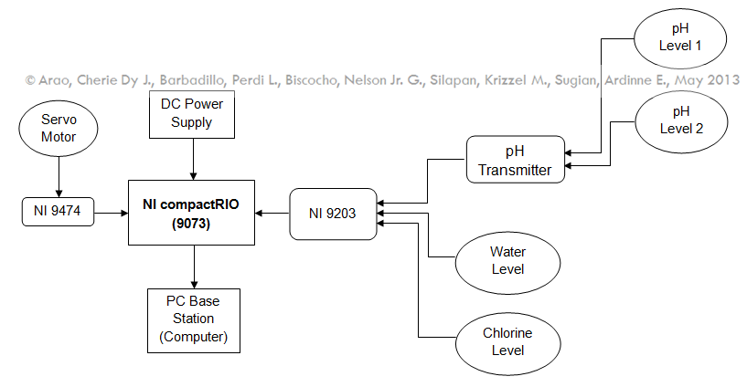
Figure 1 System Block Diagram of Real-Time Monitoring of pH and Water Level and Automation of Chlorine Control
Program Development
At the start of the process the pH and water level sensors in the tank, comes in contact with the sewage treatment water to detect whether it is an acid, base, or neutral and at the same time identify the water level. The system distinguishes treated water with pH level higher than nine as base, pH lower that six as acid and an obtained pH value equal to seven as neutral. For the water level of the tank, if the water level does not reach the specific critical level then the system goes back to start and back to sensing the water level, but when the water level reaches its maximum amount this may cause overflow and this activates the alarm in the server. All this, the pH and water level detection, goes through the CompactRIO and its modules where it is transmitted to the server’s PC through Ethernet cable.
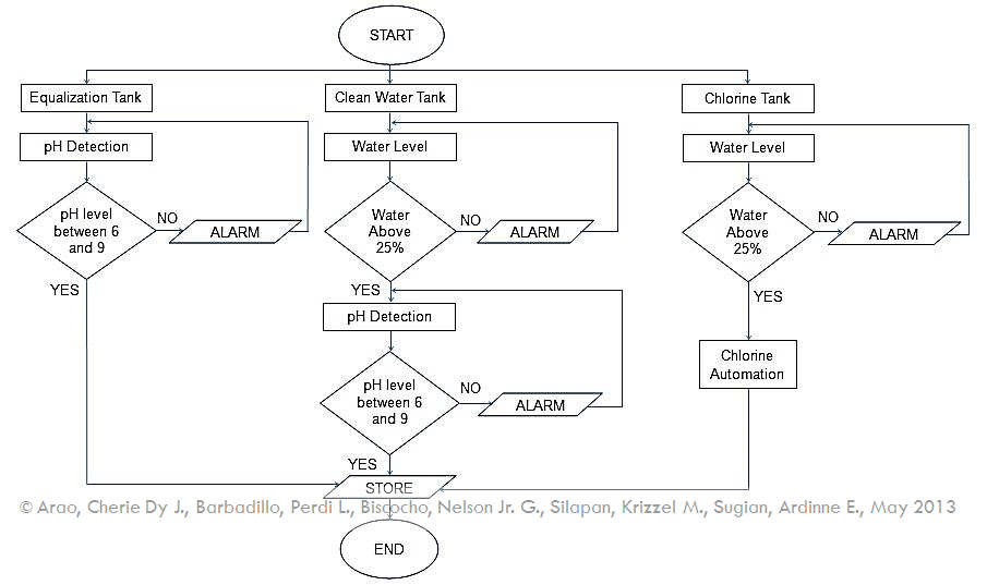
Figure 2 Flow chart of software system
Measurement Matrix
Table 1 Matrix of measurement of corresponding pH level with respect to current and its interpretation
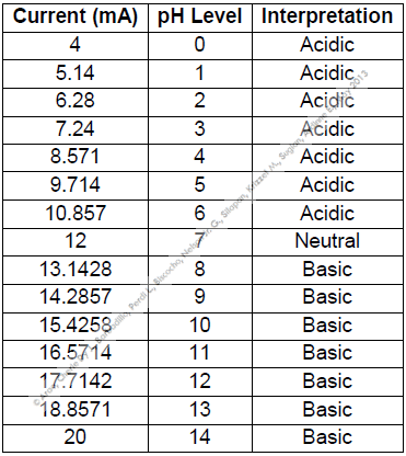
Table 2 Matrix of measurement of corresponding water level with respect to current and its percentage at 5 feet
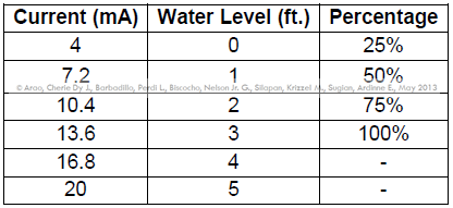
Table 3 Matrix of measurement of corresponding water level with respect to current and its percentage at 35 feet
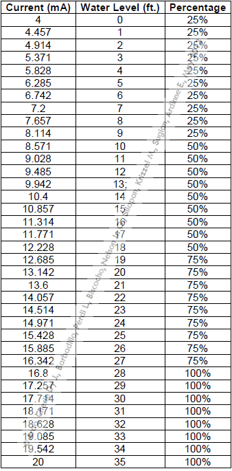
Tables 1, 2 and 3 are the matrices of the measurement system of the STP. A particular ampere reading is equivalent to a pH level same with water level except that it is expressed in feet and in percentage depending on the volume of the tank. This matrix is used all throughout the development of the system.
Final Testing
Table 4 Data Results for the Final Testing of Sensors at STP
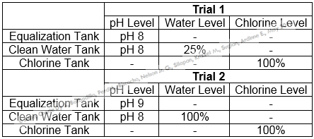
Trials 2 of the Final Testing of pH in Equalization and Clean Water tanks on Table 5 showed great improvement. pH level of 6-9 is acceptable as per DO recommendations. The water level has decreased but the pressure sensor is still able to measure it. The external chlorine tank showed no significant changes at its 100% full.
Table 4 shows the log of the data collected. One sample is equivalent to a 5 seconds of deployment in the system. It displays the results of pH and water level and indicates if the alarm has functioned.
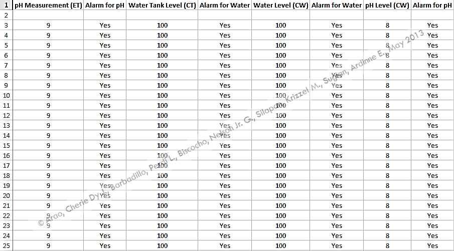
Remember that measurement may be the same in pH and water level but different in current reading. Water level reading percentage changes based on matrix of measurement. The chlorine tank can now be controlled in the office with the aid of the servo motor.
Conclusions
The Adamson University’s Sewage Treatment Plant now has system closely monitoring the pH and water level of the Equalization and Clean Water tanks in real-time without having to take samples and analyze it in a laboratory outside the University. Chlorine tank is automated for complete monitoring and treatment and data logging reports are generated for perusal.
Benefits of LabVIEW and NI Tools
The project was made possible by using NI CompactRIO9073 integrated system that has real-time processor suited to the demands of the Sewage Treatment Plant (STP). With its ruggedness, it can stand inevitable weather conditions in the site of the project. The built-in Ethernet port makes it possible to communicate over the network from the site to base station.
The NI 9203 C series data acquisition module that has 8 analog current input channels is the main frame of the pH and water level sensors used in the system. On the other hand, NI 9474 can connect directly to variety of industrial devices like servo motor used in the system.
LabVIEW 2009 is the software used. Not underestimating the power of this tool, it served the team well in developing complicated Virtual Instruments (VIs) for the project. LabVIEW Real-Time Module 2009 enhances the system by setting up RT Targets to build, debug and deploy real-time applications.
Project Photos
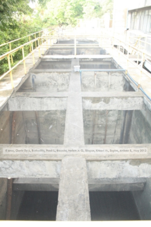
Project Site: Side 1
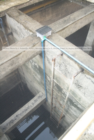
Project Site: Equalization Tank with pH probe and transmitter installed
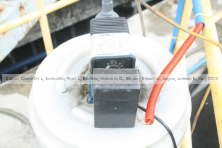
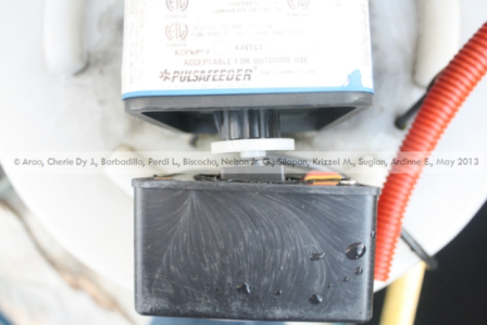
Project site: pH transmitter at Equalization Tank
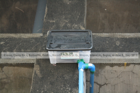
Project Site: pH transmitter in Clean Water Tank
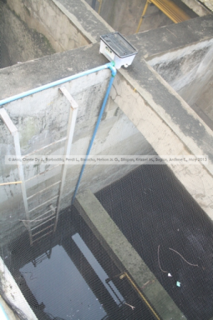
Project Site: pH and water level sensor installed
Project Site: Chlorine Tank with Servo motor installed
Project Site: Servo motor installed at the knob of the tank to control the flow
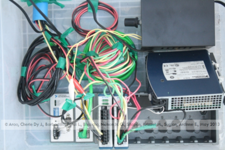
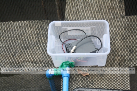
Project Site: Central Processing Unit (forgive the bad wirings, photo taken during the development period.  )
)
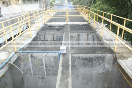
Project Site: Side 2
VI Codes
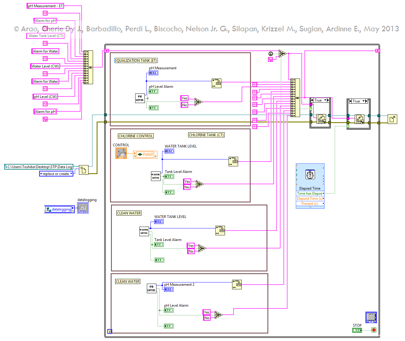
Final VI. This is composed of Sub-VIs to complete the process.
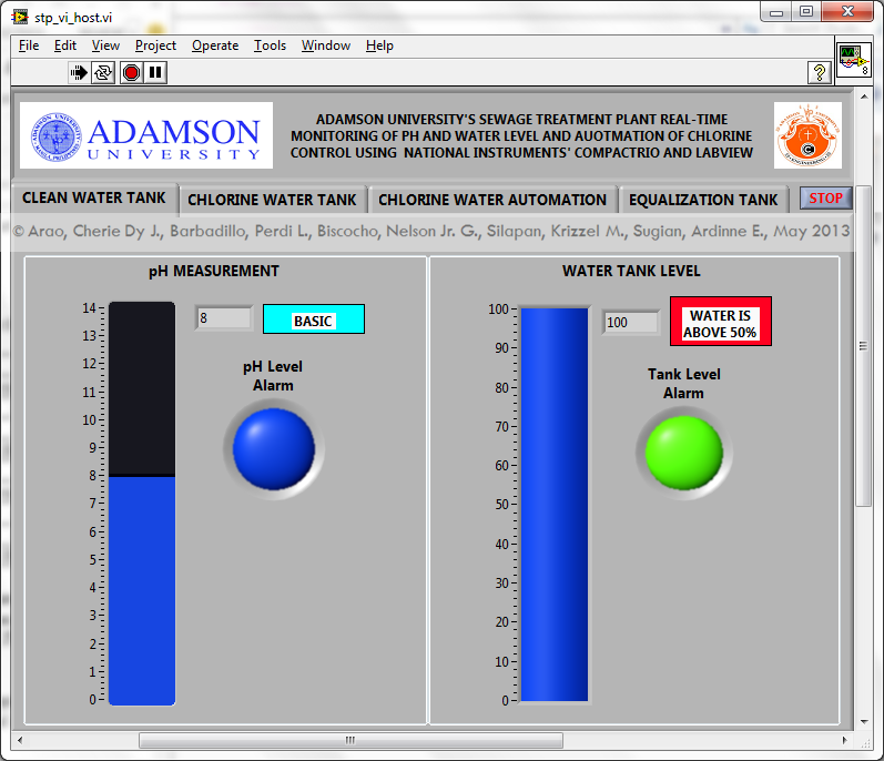
User Interface of the project.
Level of Completion/Time to Build
The project is on beta to fully functional phase. During the development of the project, the site is functioning well that's why we were able to conduct tests and measurement. As of today, it is under maintenance to achieve better performance and to maximize the system installed.
It took the team a year to develop the project. Including documentation and installation. (Note: This is a thesis project. A term in needed for a proposal and another term for project implementation.)
Poster
(See attachment)
Others
Copyright May 2013 (Paper and Program)
- Mark as Read
- Mark as New
- Bookmark
- Permalink
- Report to a Moderator
good job guys!
- Mark as Read
- Mark as New
- Bookmark
- Permalink
- Report to a Moderator
big project. where is download button?
- Mark as Read
- Mark as New
- Bookmark
- Permalink
- Report to a Moderator
good idea 
- Mark as Read
- Mark as New
- Bookmark
- Permalink
- Report to a Moderator
What are the hardware requirements for this project and their specifications related to National Instruments..
