- Document History
- Subscribe to RSS Feed
- Mark as New
- Mark as Read
- Bookmark
- Subscribe
- Printer Friendly Page
- Report to a Moderator
- Subscribe to RSS Feed
- Mark as New
- Mark as Read
- Bookmark
- Subscribe
- Printer Friendly Page
- Report to a Moderator
Overview
Code Developed in the Lab of Dr. Murat Torlak at University of Texas at Dallas, and ported to LabVIEW Communications 1.0 by National Instruments. The application decodes and displays 802.11b network SSIDs generated by an ad-hoc network from your computer's wireless adapter.
Description
This example utilizes a state machine to scan for WiFi packets and extract the associated SSID of the detected network signal. This state machine is executed as follows:
1. Initiate: Initiates the USRP session and fetches a set of data to aid in eliminating transients
2. Read: Fetches USRP data and performs a simple energy detection to identify a WiFi packet of interest between channels 7 and 17
3. Trigger Found: When a trigger is found, the USRP session is aborted to allow for data processing
4. Process: The SSID decoding is done in the Decode SSID.gvi in this state of the state machine. Decode SSID.gvi performs a frequency offset correction and then demodulates and de-scrambles the data according to the spec. An ASCII look-up table then translates the bits into characters. Some logic is then executed to ensure the data is valid before logging it into an array and displaying it on the front panel.
Troubleshooting: Occasionally there may be characters that are not recognized properly. Performing some equalization and adding a few other tuning parameters should minimize their occurence.
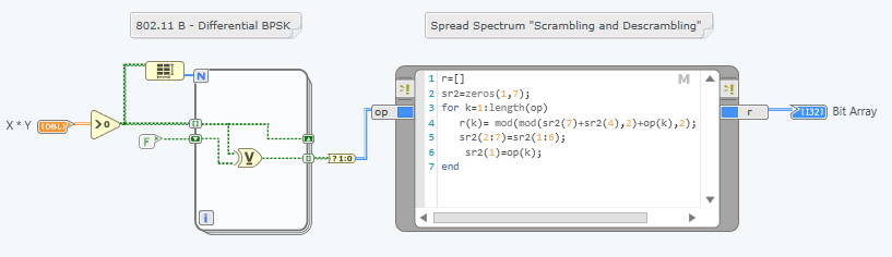 Figure 1: Diagram of Descramble and Demodulate.gvi |
Steps to Implement or Execute Code:
Set up your computer as an Ad-Hoc 802.11b network
(steps may vary depending on Operating System)
- In Windows: open the "Network and Sharing Center"
- Click 'Manage Wireless Networks'
- Click 'Add'
- Click 'Create an Ad Hoc Nework'
- Click the 'Save this Network' tick box
Configure your wireless adapter for 802.11b (if needed)
- From 'Network and Sharing Center' select 'Adapter Settings'
- Right click the wireless adapter and select 'Properties'
- Click 'Configure' at the top of the 'Wireless Connection Properties' page
- Look for something about Ad Hoc Channel in the 'Advanced' tab (screen shot below)
- for my computer, 0 = b and 1 = g Ad Hoc network. I set it to 0.

Figure 1: Configuring wireless adapter properties
Begin transmitting beacon signals
- Left click on the wireless icon in the Windows Taskbar
- The Ad-Hoc network created previously should appear in the list of possible networks to connect to
- Double click this network and you're live! Hovering over the ad-hoc network will tell you the status - it is transmitting if it displays 'Waiting for Users', see figure 2.

Figure 2: Checking the status of the wireless test network
Run the LabVIEW code to identify and decode your broadcasted network
1. Open Main USRP WiFi Demo.gvi
2. Observe the panel (shown in Figure 3)
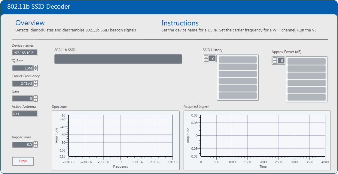 |
Figure 3: Front panel of Main USRP WiFi Demo.gvi
3. Configure the device names control to the IP address of your USRP device (typically 192.168.10.2)
4. Verify the remaining parameter are set as follows:
| Parameter | Value |
|---|---|
| IQ Rate | 5M |
| Gain | 10 |
| Carrier Frequency | 2.412G |
| Active Antenna | RX1 |
| Trigger Threshold | 0.5 |
5. Run the VI and observe the decoded SSIDs. An example of the output is shown in Figure 4:
|
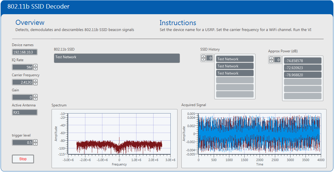
Figure 4: Execution of Main USRP WiFi Demo
Troubleshooting
If you receive errors regarding potentially mis-aligned packets:
- Ensure you are using Ethernet adapter drivers from the manufacturer of your Ethernet adapter. Native Windows drivers do not always offer the best performance nor the flexibility to adjust advanced settings.
- Try increasing the Tx and Rx buffers in your Ethernet adapter settings. This will typically be found in Windows Device manager: right-click >> properties of your Ethernet adapter (the one connected to your USRP) >> Advanced Settings >> Performance Options >> Tx Buffer/Rx Buffer. Once you've increased the values (1024 or 2048 are good settings to try), reboot your system.
Requirements
Software
- LabVIEW Communications Sysytem Design Software 1.0
Hardware
- USRP-2921, USRP-2922, USRP-2932
- Vert2450 Antenna
Additional Images or Video
LabVIEW 2014 version of this example is available here.
Click Here to discuss this and other examples on the LabVIEW Communications Discussion Forums.
- Mark as Read
- Mark as New
- Bookmark
- Permalink
- Report to a Moderator
Hi C-Dav,
I tried to open the project in LabVIEW NXG 2.1, but the Decode SSID.gvi is throwing an error "Load Error: An error occurred while trying to load "Decode SSID.gvi". The source file format is invalid."
Is it due to the NXG version or am I missing something. It would be great if you could help me out.
Thanks and Regards,
Nishanth
