- Subscribe to RSS Feed
- Mark Topic as New
- Mark Topic as Read
- Float this Topic for Current User
- Bookmark
- Subscribe
- Mute
- Printer Friendly Page
Laser Sensor Voltage Does Not Settle At Zero
09-14-2011 03:32 PM
- Mark as New
- Bookmark
- Subscribe
- Mute
- Subscribe to RSS Feed
- Permalink
- Report to a Moderator
Hello wise ladies and (mostly) gentlemen. Have a problem for you that has got me quite frustrated.
My current setup:
Wenglor Reflex Laser Sensor: http://www.wenglor.com/index.php?id=346&L=0%27&tx_wsproductlister_pi1%5BArtikelNR%5D=YR24PCT2&tx_wsp...
SCC-A10
SC-2345
DAQ 6036E
Labview (can't remember what version).
The sensor is connected to a 24V power supply, with the output of the sensor to the positive terminal of the SCC-A10, and the neutral of the power supply to negative terminal. Theoretically, (I measured these voltages with a multimeter) it jumps from around 23.2V to 0V, depending on if it is in NO (Normally Open) or NC mode. When everything above is hooked up, and my VI running, I get the output of the sensor going crazy when it is supposed to be sitting at 0V. The 23.2V side of things is fine however.
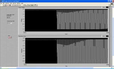
The left side of the graph is for output of 23.2V, right side is the theoretical zero. But instead it seems to be going crazy between 2.32V and -1.5V (SCC-A10 is a voltage divider by 10). WHY??????
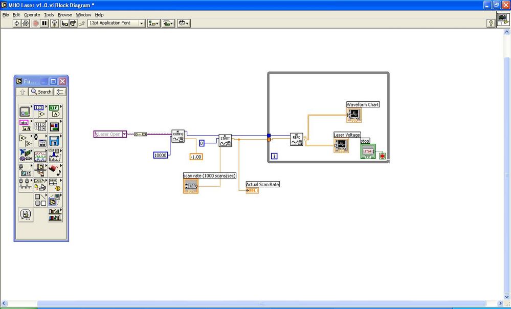
Block diagram of VI:
Input mode is referenced single ended, sensor range is -10 to 10 V. Connected on ACH6 or 14.
HELP PLEASE!!
09-15-2011 12:47 AM
- Mark as New
- Bookmark
- Subscribe
- Mute
- Subscribe to RSS Feed
- Permalink
- Report to a Moderator
Seems that your expected Zero is floating. Solution: Add a 10k pulldown resistor to GND
Henrik
LV since v3.1
“ground” is a convenient fantasy
'˙˙˙˙uıɐƃɐ lɐıp puɐ °06 ǝuoɥd ɹnoʎ uɹnʇ ǝsɐǝld 'ʎɹɐuıƃɐɯı sı pǝlɐıp ǝʌɐɥ noʎ ɹǝqɯnu ǝɥʇ'
09-15-2011 09:06 AM
- Mark as New
- Bookmark
- Subscribe
- Mute
- Subscribe to RSS Feed
- Permalink
- Report to a Moderator
The 10k resistor is connected between the neutral of the power supply at the SCC-A10 connection and one of the ground terminals on the SC-2345 board?
Will give it a go later on today. If this is the answer, I will be very joyous.
09-15-2011 09:28 AM
- Mark as New
- Bookmark
- Subscribe
- Mute
- Subscribe to RSS Feed
- Permalink
- Report to a Moderator
Aaaaaand a little bit of research shows that it should be connected from the sensor output at the SCC-A10 to ground, allowing the SCC-A10 to not float when the sensor output is disconnected (ie. 0V), but instead compare between ground and neutral. When the sensor is giving the 23.2V, it will flow through the SCC-A10 instead of the resistor because it is the path of least resistance.
Right?...
09-16-2011 11:45 AM
- Mark as New
- Bookmark
- Subscribe
- Mute
- Subscribe to RSS Feed
- Permalink
- Report to a Moderator
Hi InternHQ,
Your last post is correct. I do not know if this you have scene this but it is a useful reference for wiring an analog system. For your question Table 1 is particularly relevant.
http://zone.ni.com/devzone/cda/tut/p/id/3344
Regards,
Josh Brown
National Instruments
09-28-2011 12:46 PM - edited 09-28-2011 12:47 PM
- Mark as New
- Bookmark
- Subscribe
- Mute
- Subscribe to RSS Feed
- Permalink
- Report to a Moderator
So finally managed to get the resistors and get everything setup. When I attached the positive terminal through the resistor to ground, I didn't actually get any change. Still looked like the above graph. I of course said, well lets try the other way. This worked better with the 10k resistor now going from the neutral (negative) terminal to ground, but the signal (when it was supposed to be zero) would float around 0.5 by +- 0.3. Would connecting both to ground fix this? The sensor is NC, so all I really need to see is the delta, but it would be nice if the open case sat at a constant voltage.
Turns out my sensor is not sensitive enough for what I want it to do, so waiting on getting another one sent to me...will have the same setup once it gets here however.
Thanks for all the help so far, has gotten me farther than the hammer approach would have.
09-28-2011 04:44 PM
- Mark as New
- Bookmark
- Subscribe
- Mute
- Subscribe to RSS Feed
- Permalink
- Report to a Moderator
Please draw a schematic of your setup (you might need it for your documentation anyhow 😉 )
Henrik
LV since v3.1
“ground” is a convenient fantasy
'˙˙˙˙uıɐƃɐ lɐıp puɐ °06 ǝuoɥd ɹnoʎ uɹnʇ ǝsɐǝld 'ʎɹɐuıƃɐɯı sı pǝlɐıp ǝʌɐɥ noʎ ɹǝqɯnu ǝɥʇ'
09-29-2011 12:43 PM
- Mark as New
- Bookmark
- Subscribe
- Mute
- Subscribe to RSS Feed
- Permalink
- Report to a Moderator
Below is what I tried first, but didn't seem to work...
And then this, which gave me the drop but still had noise.
Thoughts?
09-29-2011 01:44 PM - edited 09-29-2011 01:46 PM
- Mark as New
- Bookmark
- Subscribe
- Mute
- Subscribe to RSS Feed
- Permalink
- Report to a Moderator
You need to power the sensor directly from your supply, not through the SC module. (24V supply output + and - to the sensors + and - inputs)
And then tie - of supply to SC - input.
The output of the sensor is on the A/A not terminal, this would be wired to the SC + input.
-AK2DM
"It’s the questions that drive us.”
~~~~~~~~~~~~~~~~~~~~~~~~~~
09-29-2011 01:52 PM
- Mark as New
- Bookmark
- Subscribe
- Mute
- Subscribe to RSS Feed
- Permalink
- Report to a Moderator
Well I am an idiot, drew that drawing completely incorrect. You are right, and that was how I had it wired, just blanked when I was drawing it.
Corrected drawings:
Didn't work...
Worked but had noise when open...


