- Document History
- Subscribe to RSS Feed
- Mark as New
- Mark as Read
- Bookmark
- Subscribe
- Printer Friendly Page
- Report to a Moderator
- Subscribe to RSS Feed
- Mark as New
- Mark as Read
- Bookmark
- Subscribe
- Printer Friendly Page
- Report to a Moderator
Using LabVIEW and NI myRio to create a Robot Car Wi-Fi controlled
Contact Information
Competition Year: 2016-2017
University: University of Valencia
Team Members: David Brotons Alcázar, Antonio Alcarria Moraga.
Faculty Advisers: Edith Asunción Navarro, Silvia Casans.
Email Address: dabroal@alumni.uv.es, analmo3@alumni.uv.es
Submission Language: English
Project Information
Title: Using LabVIEW and NI myRio to create a Robot Car Wi-Fi controlled
Description: A Wi-Fi controlled Robot Car based on myRio and LabVIEW
Products:
NI Hardware
- NI myRio
NI Software
- NI LabVIEW 2016 32 bits
- NI LabVIEW FPGA
- NI LabVIEW Realtime
- NI DashBoard App
3rd Party Hardware
- 2 x 6V DC Motors: IG220053X00085R
- 2 x Motor Driver: Pmod HB5: H-bridge Driver
- 8 x LED
- 1 x Apple iPad
The Challenge:
The aim of this project is how to make an educational project using some tools from National Instruments to learn the deployment of shared variables via Wi-Fi and how to use them to control a battery powered car commanded by myRio 1900.
The Solution:
I. INTRODUCTION
Educational projects are an important part of university studies. They give the chance to test yourself and improve your skills facing new problems and situations on the several stages of the project. This kind of project should be complex enough to comprise a wide range of knowledges, but not too difficult that the main goal could be lost trying to solve a lot of situations that consume time but does not help to finish the project.
In that sense, LabVIEW is the perfect tool to develop projects, as it is possible to make big and long term projects or small and concise projects; it is left to the user’s choice.
There are some already done projects that use myRio to create a remote-control car. Some use myRio to command the car and a computer to send the driving orders [1], others prefer to use two myRios, one on the car and other to be used as a steering wheel reading the signals generated by the internal accelerometer of the myRio [2]. All the projects have in common the use of shared variables to communicate the car with the controller.
Our project also uses shared variables, as is it seems to be the best way to achieve good communications; but we wanted to build something different. Thus, we used Data Dashboard to make a GUI on an Apple iPad that reads user variables and converts them into shared variables to control the car.
The project is structured as follows: first is going to be explained the physical design and specifications of the 3D structure designed as a car chassis; then, it will be exposed the hardware part of the project, which contains the electronic and connections diagrams between myRio and the wheel motors, followed by the software developed using LabVIEW; finally, there is a review of the results and the conclusions obtained.
II. PHYSICAL DESIGN
In order to achieve a consistent and easy-to-build chassis for the car, a skeleton was designed with a 3D printer based on an existing model [3].
The car has three wheels, two front steering wheels guided by two DC motors set on the front of the chassis, one for each wheel, whereas in the back there is an idler wheel. Therefore, to control the steering, one wheel goes faster than the other to achieve the change of direction.
The chassis has been built in two parts that must be assembled to make easier the printing with the 3D printer.
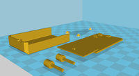
In Figure 1, can be observed the designed part of the chassis made to hold the wheel DC motors.

The second part of the chassis has holders to insert the NI myRio on the top, and all the cables and LEDs are placed inside the chassis. To use Lego wheels, two adapters for the DC motors were also made (Figure 2).
Figure 2 shows also the cover part designed to hide all the electronics.

to connect the Lego wheels to the DC motors.
The resulting chassis after assemble all the parts together is shown on the Figure 3. On Figure 3 can be seen the two wheels with their motors and the adapters that hold them together. There are also placed on the front part the headlamps, the indicators and encoders that allow to measure speed.
Fig. 3. Front view of the car.
III. HARDWARE
The hardware designed for the car consists in: two drivers to control the DC motors, two white LEDs for the headlamps, two green LEDs as indicators, two red ones on the back as brake lights and two yellow ones as reverse lights.
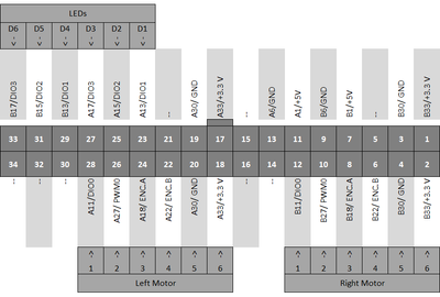
All the electronics is connected to the myRio as Figure 4 shows.
Fig. 4. Schematic to connect electronics to myRio port A and B.
The NI myRio power supply is an external rechargeable lithium battery pack connected directly to the device. According to [4], page 24, supply voltage can be 6 to 16 VDC And power consumption is up to 14W. Thus, it was chosen an Ansmann battery with nominal voltage of 14.8V and a capacity of 2600mAh.
IV. SOFTWARE
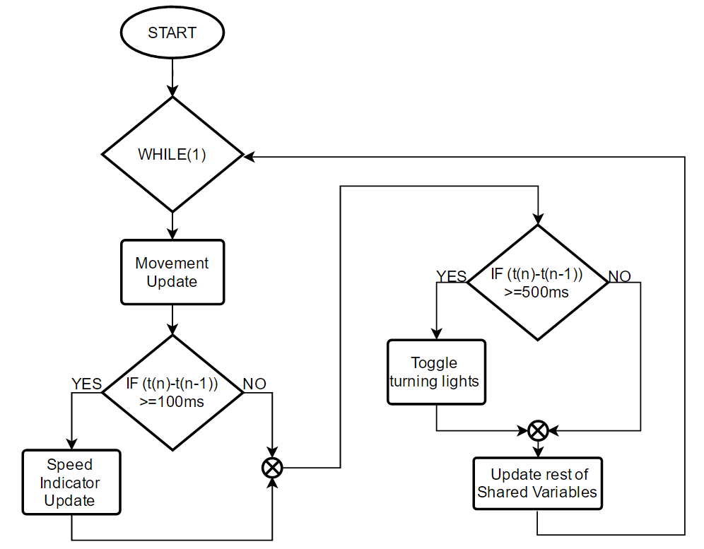
In this section, as was mentioned before, software was totally developed on LabView and it has two parts. The first one is the main program that is embedded into the myRio; it consists basically on a while loop that checks all the shared variables and updates locally those variables that have changed. On Figure 5 is illustrated the flowchart that follows the mentioned program.
Fig. 5. LabView flowchart.
The second one is the graphical user interface that is launched on an iPad using Dashboard app from National Instruments. It allows to control the car via Wi-Fi writing commands on the shared variables. The flowchart from this app is very simple and is shown on Figure 6.
Fig. 6. Data Dashboard Flowchart.
The GUI can be observed on Figure 7. We can find some indicators on it as speedometer, headlamp status indicator, parking lights, turning indicators, and a gauge that shows the driving direction.
In the bottom part of the GUI, there are two sliders that control the variables of speed and steering. Between them, on the center, there is a selector to enable or disable the motors with a P for parking and an E for enable. Finally, there is a sliding switch to control the headlamps.
Fig. 7. Control panel developed using the Dashboard app
V. RESULTS
As a result of this project, we got a fully functional Wi-Fi controlled model that responds in real time to the orders that come from the graphical user interface on the iPad.
All the objectives proposed at the beginning of the project were reached and was achieved the properly function of all the indicators and control shared variables.
Thus, several lights for the headlamps, indicators, reverse, gear, steering direction, speedometer and motor power were developed and implemented on the GUI. In that way, in add, the LEDs for the reverse indicator, headlamps and indicators were implemented on the body of the car.
On Figure 8 can be observed the final model.
Fig. 8. Resulting model.
VI. CONCLUSION
In summary, it can be said that this project has been a good approach to the real application of the using of a FPGA, in specific myRio, to develop a whole construction project from zero.
This project requires to apply several skills on electronics and LabView programming and that can be very useful to learn and train more on this fields. Therefore, in many ways this project works well as a challenge for the maker.
In add, is a very interesting project since the advances and improvements made by the maker are very visible in each phase of the project, which is more rewarding from a student or amateur approach.
VII. REFERENCES
[1] T. Petru, "myRIO remote controlled vehicle with video streaming", Forums.ni.com, 2017. [Online].
Available: http://forums.ni.com/t5/Projects-Products/myRIO-remote-controlled-vehicle-with-video-streaming/ta-p/.... [Accessed: 23- Feb- 2017].
[2] E. Coltoff, "myRio Remote Controlled Car", Behance.net, 2016. [Online]. Available: https://www.behance.net/gallery/45438481/myRio-Remote-Controlled-Car. [Accessed: 23- Feb- 2017].
[3] A. Schmid, "myRIO Balancing Robot - Getting Real!", Forums.ni.com, 2013. [Online]. Available: http://forums.ni.com/t5/myRIO-Balancing-Robot/myRIO-Balancing-Robot-Getting-Real/gpm-p/3527763. [Accessed: 24- Feb- 2017].
[4] National Instruments. USER GUIDE AND SPECIFICATIONS NI myRio-1900. Available: http://www.ni.com/pdf/manuals/376047c.pdf
Level of completion: Beta version
Time to build: 3 months


