From Friday, April 19th (11:00 PM CDT) through Saturday, April 20th (2:00 PM CDT), 2024, ni.com will undergo system upgrades that may result in temporary service interruption.
We appreciate your patience as we improve our online experience.
From Friday, April 19th (11:00 PM CDT) through Saturday, April 20th (2:00 PM CDT), 2024, ni.com will undergo system upgrades that may result in temporary service interruption.
We appreciate your patience as we improve our online experience.
03-17-2016 04:10 PM
Hey all,
I have problem using the eqep dx model to capture the speed, hope some body can help.
Firstly, I used the same model before for a different motor so I think I know how the mothed works and I I know the logic
Basically I test the model using a open loop volt/herz method(I verified the speed using techo meter) the formula should be 40e6/(clock devider*2)*1/(cpr*4) this will gives the speed in herz
I used it before the model gives me the right results straight .
Now with the same model different motor I get some random number as output and the wired thing is even I switched back to the old motor it still gives me the wrong output
I attachment the code, the main vi is the back9606.vi
Hopefully somebody can help me out
Thank you !!
03-17-2016 04:15 PM
Make sure the FPGA is not in simulation mode.
03-17-2016 04:18 PM
my fpga still gnerates the swithch signal to dtive the motor so i think it' in the FPGA mode
03-22-2016 01:12 PM
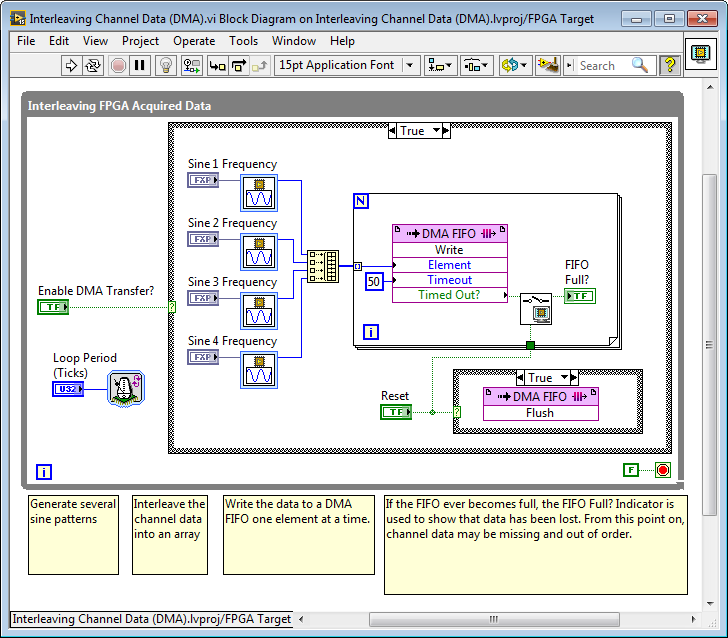
You are doing DMA transfer of three interleaved channels without any timeout or error handling. Also, the default value for the "plot rate" loop timer is set to zero, causing the loop to run at > MHz rates when the FPGA first starts running. Therefore most likely the DMA buffer is overflowing, causing you to loose the indexing sequence for the three channels. That will cause your display of the data to look random, since the data from one channel is mixing with the data from another channel when you de-interleave. Is your FIFO Full indicator (x .or. y?) indicating a true status? If the DMA buffer overflows, you need to perform a Flush/Clear method to clear it, or read all of the elements until it is empty. It also indicates you have lost data. Note that you should also initialize the FIFO Full register to False, or the value will be latched from one run to the next of the FPGA application unless the entire FPGA application is reset.
Here is an example with some recommended changes. The default loop rate is 40,000 ticks (1 millisecond). The FIFO Full? indicator detects if overflow occurs. The Reset button can be used to flush the FIFO if overflow occurs, without requiring you to reset the entire FPGA application from the RT controller. The timeout is non-zero (50 ticks), making it more robust if the PCI/AXI bus is full, since the FPGA application can wait for the bus bandwidth to become available. Finally, there is a control to Enable DMA Transfer? so it doesn't start until the RT application is ready.

Note that if you add logic to send a finite number of samples in a burst rather than streaming the data continuously, you can sample at extremely high rates that are much faster than the RT controller application could handle continuously (i.e. 100 kHz to 1 MHz or even faster).