- Subscribe to RSS Feed
- Mark Topic as New
- Mark Topic as Read
- Float this Topic for Current User
- Bookmark
- Subscribe
- Mute
- Printer Friendly Page
Video: FPGA-based Real-Time Hardware-in-the-Loop Simulation and Rapid Prototyping of Power Electronics
11-09-2011 10:19 PM
- Mark as New
- Bookmark
- Subscribe
- Mute
- Subscribe to RSS Feed
- Permalink
- Report to a Moderator
Access the high definition version of this video tutorial here. Access the latest version of the open source LabVIEW FPGA code here.
This is video tutorial showing a real-time simulation of a three phase single-level inverter with RLC filter and load. The real-time HIL simulation is executed in FPGA hardware using LabVIEW at a 1 MHz loop rate. A basic sine-PWM control system is also executed at a 500 kHz in the FPGA with an NI 9401 module used for communication between the HIL and RCP loops.
Below is the inverter circuit with the component values used in the LabVIEW FPGA state-space simulation. This three phase load circuit is converted to state-space as described in this paper (link).
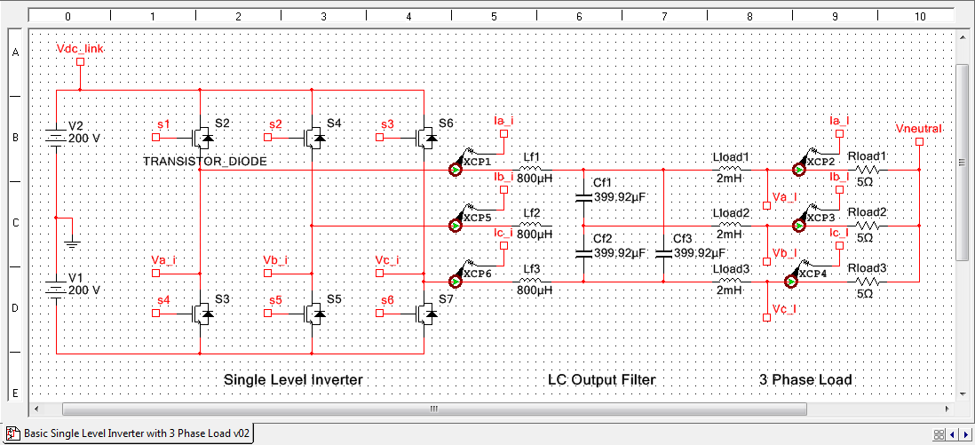
In demonstration video, the power switches are simulated as ideal ON/OFF switches. The inputs to the state-space model are the switch output voltages (Va_i, Vb_i, Vc_i). This particular state space implementation executes at speeds up to 3.57 MS/s (28 ticks of a 100 MHz FPGA clock). A discrete time, fixed point Runge-Kutta 1 (Euler) solver is used for integration. The standard Matrix*Vector multiply blocks for LabVIEW FPGA are modified to use FPGA RAM for the A matrix coefficients, enabling them to be changed while the simulation is running.

The state-space matrix for the three phase filter and load is as follows:

States (X):
VLAB
VLBC
VLCA
IiAB
IiBC
IiCA
ILAB
ILBC
ILCA
Inputs (u):
ViAB
ViBC
ViCA
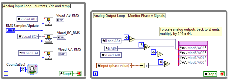
An FPGA-based control system acquires the load voltages (Va_l, Vb_l, Vc_l) at and calculates the RMS value of the line-to-line voltage Vab_l. For 50 or 60 Hz operation, the RMS Samples/Update should be set to 1000*N or 833*N respectively, where N is the number of cycles on which each calculation should be based. The RMS calculation output is invalid before the first cycle- special code should be added to handle this case (not shown). Also, the AB line-to-line voltages and currents are sent to an NI 9263 analog output module for monitoring purposes.
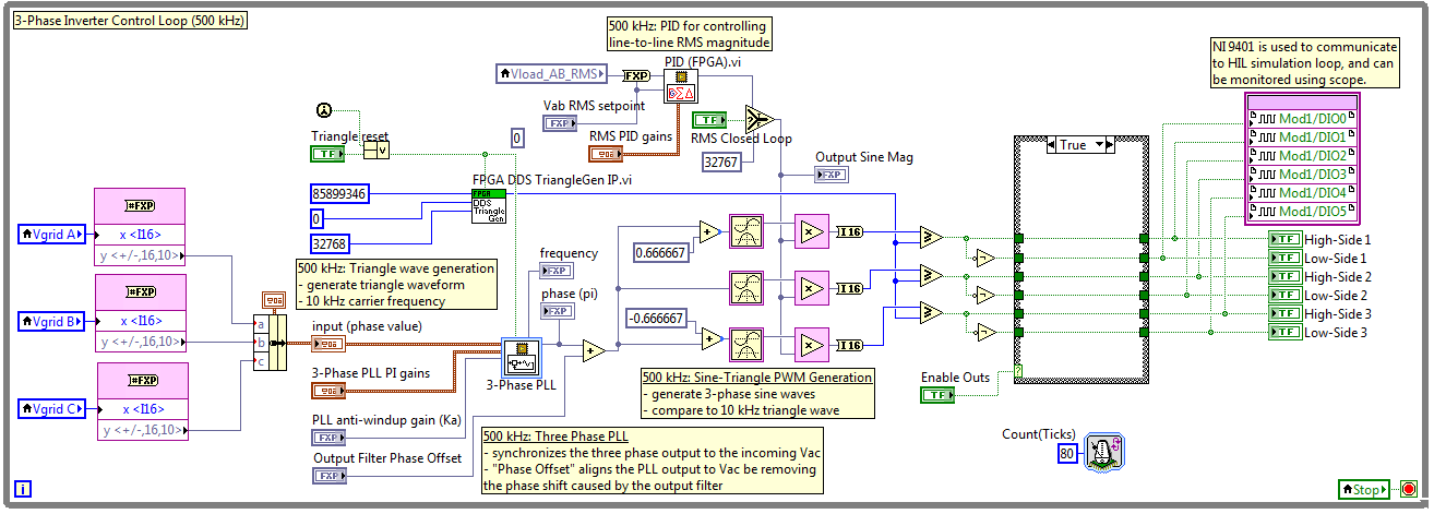
The Vload_AB RMS signal is the process variable input to a PID control loop running in the FPGA at 500 kS/s, which regulates the amplitude of the output voltages by controlling the PWM duty cycle. A sine-triangle PWM generation scheme is used, with the phase controlled by a 3-phase PLL IP core (included on the palette with LabVIEW FPGA 2011).
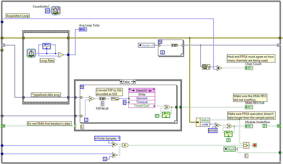
The state (vector c) values are streamed to the real-time processor RAM using direct memory access (DMA), using the CompactRIO Waveform API.
The front-panel of the LabVIEW Real-Time application provides a graphical user interface for diagnostics, testing and tuning. Note the visible harmonics in the load current power spectrum at integer multiples of the grid frequency.
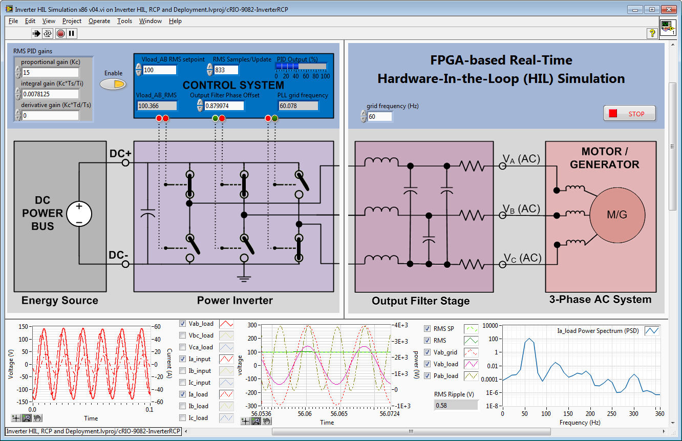
Operation at a 50 Hz grid frequency. Note that RMS Samples/Update is changed to 1,000 so the RMS calculation updates once per cycle.

Notes:
- The illustration on the front panel of the LabVIEW Real-Time application is misleading- in this particular case we are simulating a resistive load rather than a motor/generator.
- It is more common to use two different FPGA targets for HIL testing purposes. One target, with maximum FPGA processing horsepower such as NI FlexRIO, acts as the power electronics simulator. The other target acts as the rapid control prototyping platform for the control system. To communicate between the FPGAs, either a physical connection (cables) or peer-to-peer streaming via the PXI Express backplane is used.
Source Code:
- Access the latest version of the open source LabVIEW FPGA code here, which is now based on floating point IP cores from the LabVIEW FPGA Floating Point Toolkit.
To learn more and download a design guide PDF, join the developer community group at ni.com/powerdev.
04-09-2016 10:12 PM
- Mark as New
- Bookmark
- Subscribe
- Mute
- Subscribe to RSS Feed
- Permalink
- Report to a Moderator
Hello sir,
This tutorial was really helpful to us.
Can you send this coding to sudhasrimathismile@gmail.com. when I tried to workout this coding it showing some errors.
Thank you sir.
04-10-2016 01:30 AM
- Mark as New
- Bookmark
- Subscribe
- Mute
- Subscribe to RSS Feed
- Permalink
- Report to a Moderator
Impressive piece of work. Thank you for sharing this material.
04-10-2016 10:25 AM
- Mark as New
- Bookmark
- Subscribe
- Mute
- Subscribe to RSS Feed
- Permalink
- Report to a Moderator
https://decibel.ni.com/content/message/132425#132425
Thank you! The code can be found in the master power electronics and control IP library (linked above). There are speed optimized and resource optimized versions of the state-space solver. Go to that page and search on state-space to find the path location. Let me know if you have any feature requests- I'm thinking of doing some new flavors. You might also want to check out the proportional resonant controller with multi harmonic compensation, which shows how you can use the controllability form of state space to minimize the number of multiply and add operations just by putting the state-space model in that form after discretizing.
You might also be interested in the transfer function solver. I'm also thinking about doing a zpk discrete solver since I think it will make it easier to precisely located the poles and zeros with discrete single precision math.
All of these are written as multichannel cores, so you can do N number of solvers with consuming any more FPGA resources by storing the state for each channel in FPGA RAM- only the speed changes as you compute more channels.
07-05-2016 06:33 AM
- Mark as New
- Bookmark
- Subscribe
- Mute
- Subscribe to RSS Feed
- Permalink
- Report to a Moderator
Dear Sir,
What are the changes to be made in PID block of 50hz inverter to produce 400hz AC wave.Kindly help us sir.
Thank You.
