- Subscribe to RSS Feed
- Mark Topic as New
- Mark Topic as Read
- Float this Topic for Current User
- Bookmark
- Subscribe
- Mute
- Printer Friendly Page
SbRIO GPIC and open loop PWM
04-20-2016 10:08 AM
- Mark as New
- Bookmark
- Subscribe
- Mute
- Subscribe to RSS Feed
- Permalink
- Report to a Moderator
Hi all,
I am facing some issues with the sbrio GPIC. Here we go: 
1) Generation palette ---> Sinewave generator
here are my settings
frequency (default) 50.0027 Hz
amplitude 1
1024 16-bit elements look-up table
I give as an external terminal the frequency (period/tick) i.e. desired output frequency/40MHz (on board clock)
The problem is that if I try to plot the output I do not get a smooth sinewave but an awful one, which proves to be a problem since I am implementing an open-loop PWM controller, is it related to the fact that I am using a loop timer equal to 20?
2) Have you got any experience in choosing the loop timer and the deadtime for the NI9683 Rising edge delay? (in the example the loop timer is 20 and the delay time is 4, how can I choose it wisely?)
3) In order to generate also a triangular wave I am using the same structure as in https://decibel.ni.com/content/docs/DOC-2387 but I cannot get how much is the base carrier frequency, have you any idea about it? Or have you figured out another solution to have a triangular wave where frequency can be changed on the fly?
Thank you very much
Alberto
04-21-2016 01:18 AM
- Mark as New
- Bookmark
- Subscribe
- Mute
- Subscribe to RSS Feed
- Permalink
- Report to a Moderator
Hi Alberto,
I can try to answer to questions 2 and 3. I generated the triangula waveform by implementing a counter on the FPGA, as it is done usually in DSP or uC. Accordingly, you can increase the counter frequency to have a better pulse positioning. In my case 1/120 MHz is the PWM resolution. Master control loop can be synchronized where you want with respect to the PWM counter.
You can download the code here www.ped-board.com
go to the 'download' section and then 'projects'. The PWM modulator is in all the projects.
Even if it was done for the sbrio-9651, it is completely portable thanks to the LabVIEW environement 
Question 1. How do you plot the sinewave? Is it generated from the RT target and then data are sent to the FPGA or it is directly generated into the FPGA?
Chhers,
AL3
04-24-2016 02:22 PM
- Mark as New
- Bookmark
- Subscribe
- Mute
- Subscribe to RSS Feed
- Permalink
- Report to a Moderator
Hi
thank you for your answer, I'll have a look on the website you suggested.
Right now the sinewave is generated directly into the FPGA, the plot is done by means of a vi under the simulation mode of execution
04-25-2016 01:07 PM
- Mark as New
- Bookmark
- Subscribe
- Mute
- Subscribe to RSS Feed
- Permalink
- Report to a Moderator
On the FPGA, I generated 3 sinewaves using memory registers and a VI as generating file.
Code is in the 'repetitive control' project on the ped-board website.
If I am not wrong, plot is not supported in FPGA, if you attach the code it would be better to understand your issues...
Cheers,
AL3
04-25-2016 02:25 PM
- Mark as New
- Bookmark
- Subscribe
- Mute
- Subscribe to RSS Feed
- Permalink
- Report to a Moderator
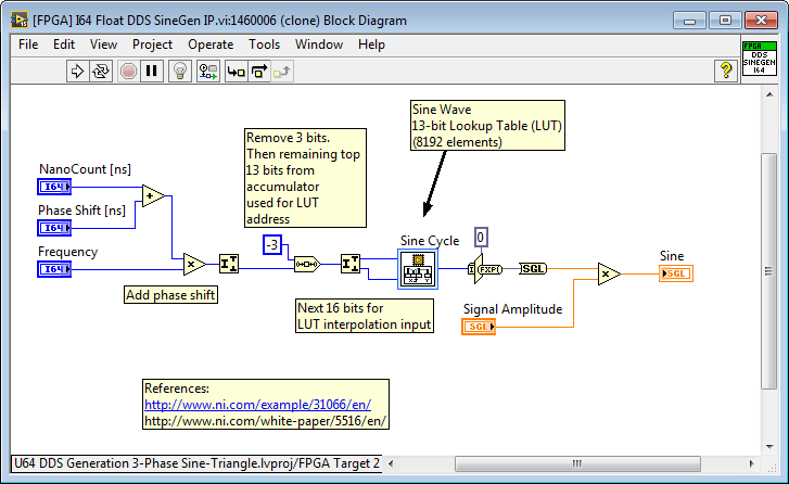
The Sine Wave Generator function in LabVIEW FPGA uses a technique called Direct Digital Synthesis (DDS) to produce the waveform. As noted in the help documentation, the frequency of the sinewave produced will not be correct in simulation unless you adjust for the simulation loop rate. In other words, if you are running at a simulated 20 tick time interval (where each tick represents 25 nanoseconds), then the frequency required to produce a 50 Hz sinewave is 20*1.25007E-6 rather than the default value of 1.25007E-6 periods/tick set by the Express VI.
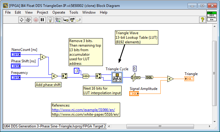
Direct Digital Synthesis (DDS) can also be used to generate the triangle waveform for sine-triangle PWM, by changing the look up table. You can find more background on DDS in these links (white paper, app note).
Here is an example that shows how to do it, using an open source DDS generator which I modified to use an I64 nanosecond time reference and floating point output waveforms. It also shows the sine and triangle waveforms in FPGA simulation mode (screenshot below).
DDS Sine Generator:
DDS Triangle Generator:
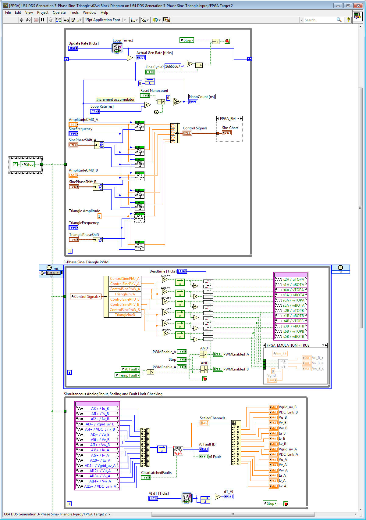
Complete Control Application:
Simulation Screenshot:
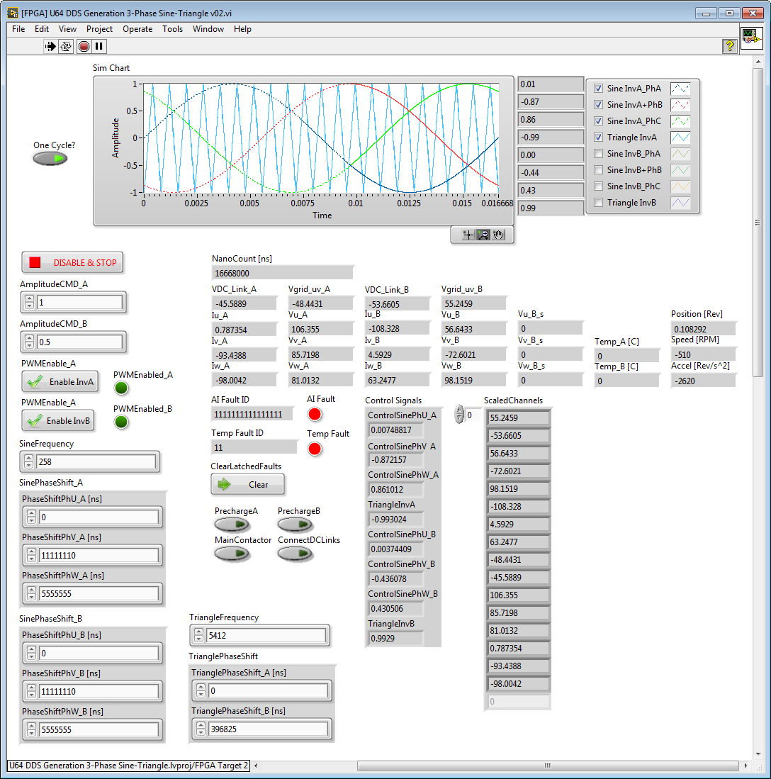
Notes:
1. The sinewaves are configured for 60 Hz, the triangle waves are configured for 21*60 = 1260 Hz).
2. The phase angle offsets are set in nanoseconds.
3. Note that in the simulation run above, I haven't hooked up a LabVIEW FPGA Desktop Execution Node that allows me to control the I/O node values (for example, based on a Multisim circuit co-simulation of the power converter). Therefore the I/O values are random numbers.
The example code above also includes a new IP core for high speed floating point scaling and fault limit checking. With external conversion from I16 to floating point in the calling while loop (as shown in this application lower loop screenshot above), it typically takes 30 ticks (0.75 microseconds) total to complete.

You can find this example code in the power electronics master library here:
C:\LabVIEW 2015\GPIC\GPIC Reference Design\FPGA DDS\U64 DDS Generation 3-Phase Sine-Triangle.lvproj
04-25-2016 02:36 PM
- Mark as New
- Bookmark
- Subscribe
- Mute
- Subscribe to RSS Feed
- Permalink
- Report to a Moderator
You might also be interested in the counter-based triangle generator IP core in the power electronics master library here:
C:\LabVIEW 2015\IP Cores\IP Cores - LabVIEW FPGA\Control & Signal Gen\[FPGA] Float TriangleGen (use inside SCTL).vi
Screenshot:
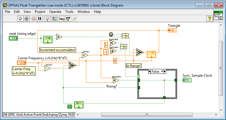
Notes:
1. The core is designed to run in a Single Cycle Timed Loop (SCTL) at 40 MHz.
2. Due to pipelining, the triangle waveform updates every two clock ticks (50 nanoseconds). Therefore, the result is naturally sampled sine triangle PWM with 20 MHz time resolution (50 nanoseconds).
For application examples, see here:
C:\LabVIEW 2015\GPIC\GPIC Grid Active Front End\NI GPIC Grid Active Front End.lvproj
Screenshot from "C:\LabVIEW 2015\GPIC\GPIC Grid Active Front End\[FPGA] Grid Tied AFE Control with FRF Stability Analysis.vi":
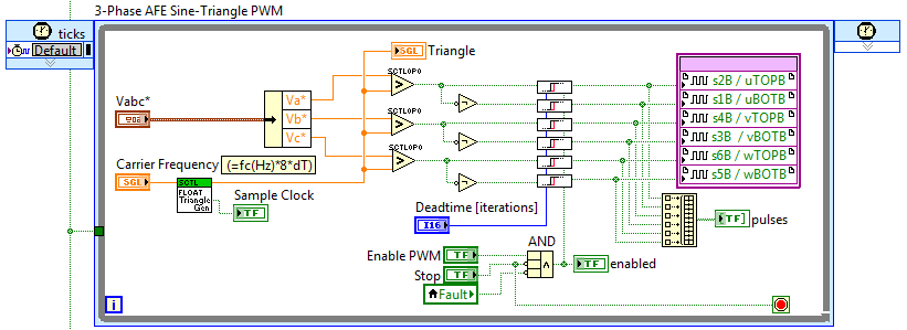
Notes:
1. This loop runs at 40 MHz. The triangle update rate is 20 MHz, so the result is 50 nanosecond naturally sampled sine-triangle PWM.
05-02-2016 02:18 AM
- Mark as New
- Bookmark
- Subscribe
- Mute
- Subscribe to RSS Feed
- Permalink
- Report to a Moderator
Thank you very much for the help.
I apologise for my delay in answering you all, thank you very much! 
05-02-2016 07:26 AM
- Mark as New
- Bookmark
- Subscribe
- Mute
- Subscribe to RSS Feed
- Permalink
- Report to a Moderator
I have a question, which is the link between the actual frequency (60Hz) and the input frequency 258, it's a factor 4.3*60, what is the meaning?
Thanks
Alberto
