From Friday, April 19th (11:00 PM CDT) through Saturday, April 20th (2:00 PM CDT), 2024, ni.com will undergo system upgrades that may result in temporary service interruption.
We appreciate your patience as we improve our online experience.
From Friday, April 19th (11:00 PM CDT) through Saturday, April 20th (2:00 PM CDT), 2024, ni.com will undergo system upgrades that may result in temporary service interruption.
We appreciate your patience as we improve our online experience.
03-31-2014 07:18 AM
Hello,
I'm having trouble understanding why the option of selecting modulation index (0-2) was included. If modulation index is equivalent to duty cycle, then is this not dependent on torque demand which would be a calculated value?
Thanks
03-31-2014 02:51 PM
I think modulation index adjust the amplitude of the triangle waveform, if the index = 1; then amplitude of the triangle wave is [-1,1], you can modify the sine wave amplitude to generate duty ratio while you keep the triangle amplitude fixed. For example your sine wave is from [-0.7, 0.7], then your real modulation ratio is 0.7.
04-04-2014 03:11 PM
That's right. In this particular triangle generation scheme (using "IP Cores\IP Cores - LabVIEW FPGA\Control & Signal Gen\[FPGA] FXPT TriangleGen with Mod Index (use inside SCTL).vi"), the amplitude of the triangle waveform is varied based on the modulation index. In this case, it's always assumed that the control sinewave has an amplitude of 1 (the value ranges between [-1, 1]).
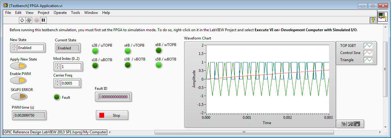
Here are FPGA co-simulation screenshots showing the state of the TOP IGBT in the half bridge (positive value indicates positive phase output voltage) in blue, the Control Sine in red, and the Triangle wave in green.
In the case of Mod Index = 1, then amplitude of the Triangle wave is 1.
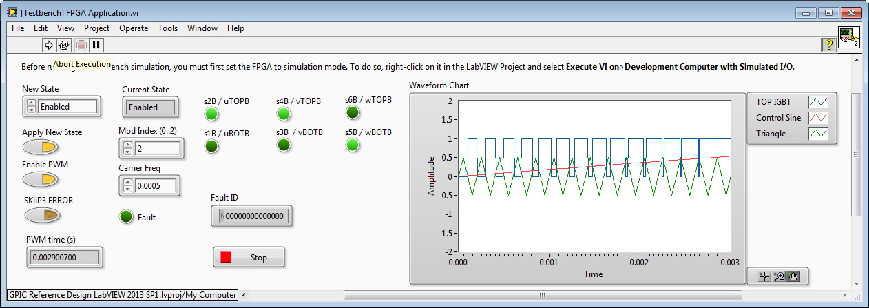
In the case of Mod Index = 2, then amplitude of the Triangle wave is 0.5. Note that the TOP IGBT is on more of the time, resulting in a higher output voltage. However, the output of the inverter (after the line reactor filter) begins to look more like a square wave than a sine wave (and therefore has higher total harmonic distortion.)
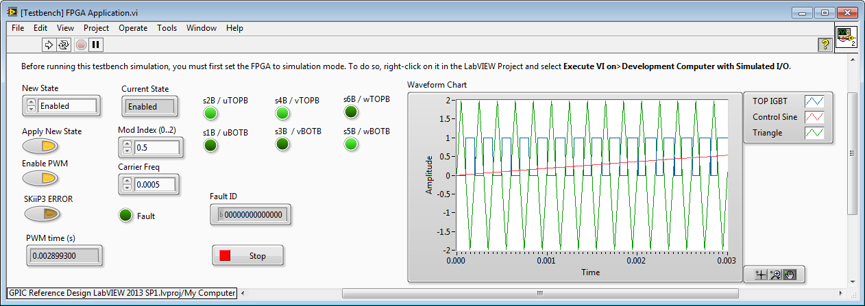
In the case of Mod Index = 0.5, then amplitude of the Triangle wave is 2. Note that the TOP IGBT is on less of the time. The inverter output voltage after the line reactor filter is a nice sinewave (similar total harmonic distortion to Mod Index = 1), however the amplitude is 50 percent less.
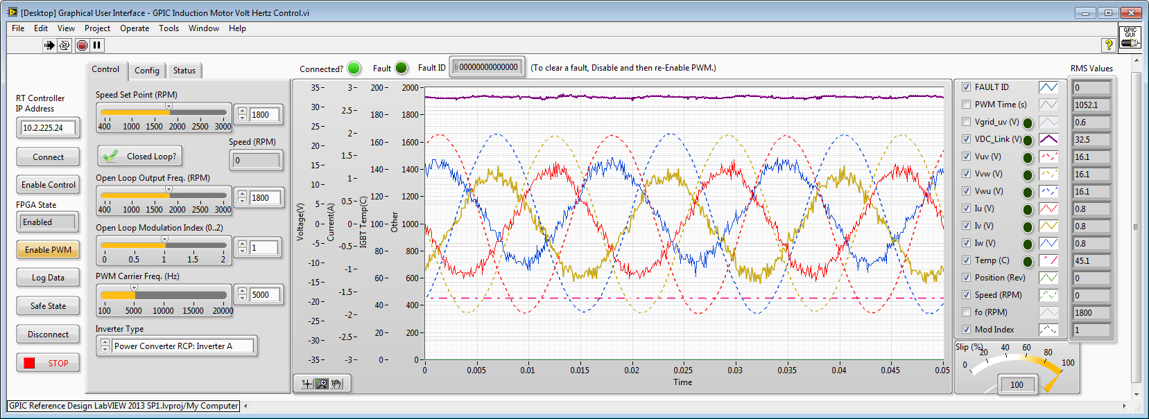
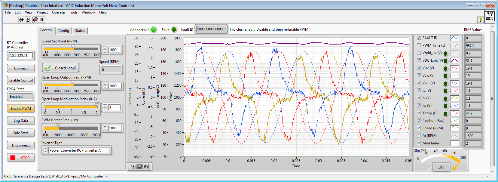
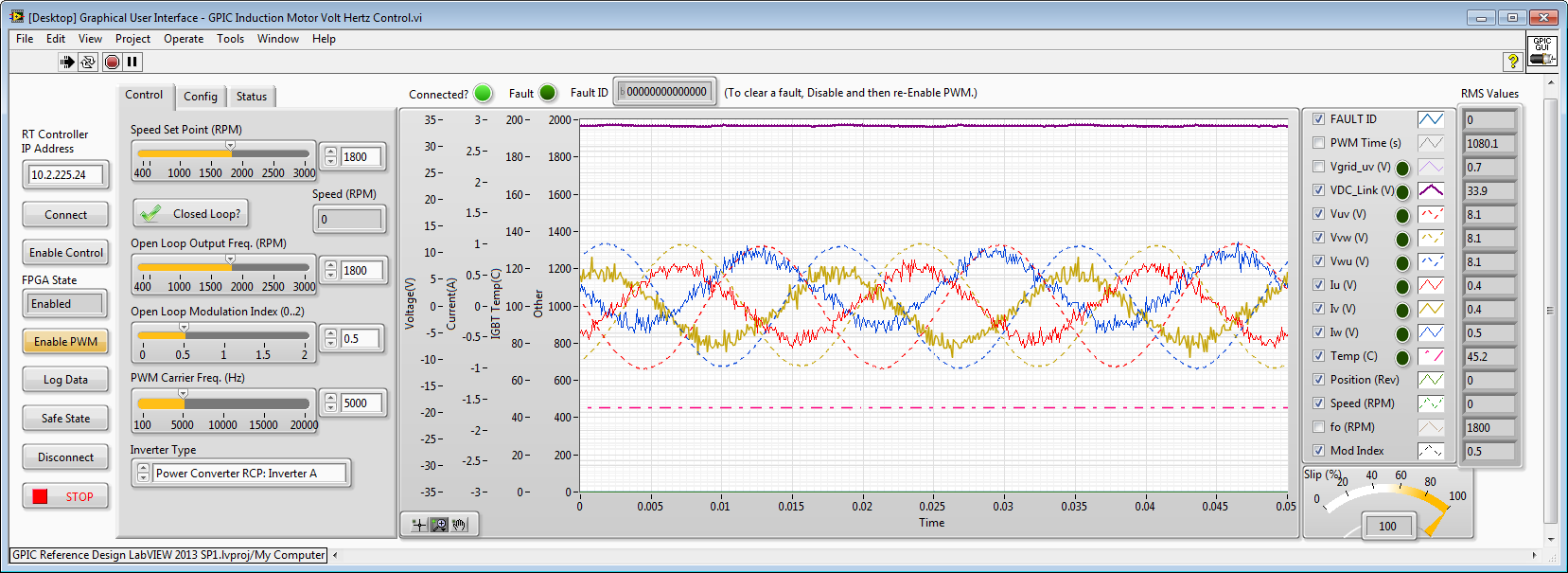
Here are waveforms from a physical 3-phase inverter with line reactor filter, controlled by the NI sbRIO GPIC.
Mod Index = 1. Line-to-line voltages are dashed traces (V_RMS=16.1). Phase currents are solid traces (A_RMS=0.8).
Mod Index = 2. Line-to-line voltages are dashed traces (V_RMS=19.1). Phase currents are solid traces (A_RMS=1.1). Note the highly non-sinusoidal, distorted phase currents. Also note that the voltage and current RMS values are not linearly proportional compared to Mod Index = 1. (If it was linearly related to modulation index, the voltage amplitude would be 32.2 V_RMS)
Mod Index = 0.5. Line-to-line voltages are dashed traces (V_RMS=8.05). Phase currents are solid traces (A_RMS=0.4). Note the highly non-sinusoidal, distorted phase currents. Note that the voltage and current RMS values are linearly proportional compared to Mod Index = 1.
Here's a Multisim schematic showing how the line reactor filter is wired in this case, as well as the component values.
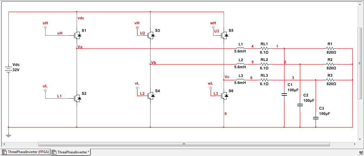
All of the code shown in this post (both the simulations and GPIC code) is available here. (Requires LabVIEW 2013 SP1.)
04-19-2019 06:34 PM
how can we make sure triangle frequency is equal to the Fc (Carrier Freq. Value = fc(Hz)*4/40e6)?
10-09-2020 06:18 AM
As u mentioned above, Mod Index of 0 will have triangular signal of high magnitude and Mod Index of 2 will have less magnitude.
Can you please specify what will be the exact magnitude of triangular signal when Mod index is 0, 1 and 2.
Also can I verify the same by making an analog out of triangular signal.
